
 0
0
 EN
EN  English
 عربى
عربى Español
 русский
If you need any help, please feel free to contact us
Home / News / Industry News / How to Choose the Right Air Flow Meter for Compressed Air: Selection & Accuracy
How to Choose the Right Air Flow Meter for Compressed Air: Selection & Accuracy
If your compressed air system lacks flow measurement, you are likely paying for air you never use. A widely cited U.S. Department of Energy statistic puts compressed air at about 10% of total industrial electricity consumption, and in many plants, 20% to 30% of that air escapes through leaks, open blow-offs, and artificial demand. An air flow meter for compressed air turns those invisible losses into actionable data. The conclusion is straightforward: choose a meter that matches your pipe size, flow range, and accuracy needs, install it with proper straight runs, and verify its readings with a routine calibration check. The rest of this article explains how to do exactly that, with practical criteria, technology comparisons, and field-proven installation advice drawn from industrial flow measurement practice.
Why measuring compressed air flow pays off
Compressed air is often described as the fourth utility, but unlike electricity or water, it is rarely metered at the point of use. That blind spot creates three costly problems. First, leaks go undetected. A single 1/4-inch leak at 100 psig can waste more than 100,000 kWh per year, enough to power several homes. Second, energy efficiency projects lack a baseline. You cannot claim savings from fixing leaks or reducing pressure if you never measured the original flow. Third, cost allocation becomes arbitrary. Production departments that use the most air may not bear their fair share of compressor maintenance and electricity, so nobody has a financial incentive to conserve.
An accurate compressed air flow meter solves all three issues. It provides real-time mass or volumetric flow, totalized consumption, and often temperature and pressure data. That information feeds energy management systems, leak detection programs, and ISO 50001 energy performance indicators. In short, measurement is the first step toward a leaner, cheaper, and more reliable compressed air system.
How compressed air flow meters work
Several flow measurement principles are used for compressed air. Each has distinct advantages and limits. The most common technologies for industrial compressed air are thermal mass, vortex, swirl, Coriolis, turbine, and differential pressure. Understanding how they operate helps you match the meter to your actual conditions rather than a catalog headline.
Thermal mass flow meters
Thermal mass meters use two temperature sensors, one heated and one reference. As air flows past the heated sensor, it carries heat away. The power required to maintain a constant temperature difference is proportional to mass flow. These meters are excellent for compressed air because they directly measure mass flow without temperature or pressure compensation, and they handle low flows well. Insertion-style thermal meters are popular for large pipes because they cost less than full-bore meters and can be installed without shutting down the line. However, they are sensitive to moisture, oil, and dirt, which can coat the sensors and drift over time. They also require a minimum velocity to avoid natural convection errors.
Vortex flow meters
Vortex meters place a bluff body in the flow stream. Alternating vortices shed from the body at a frequency proportional to velocity. A piezoelectric or capacitive sensor counts those vortices to calculate flow. Vortex meters are robust, have no moving parts, and tolerate high temperatures and pressures. They work well for compressed air when the flow is clean and dry, and they offer good accuracy over a moderate turndown ratio, typically 10:1 to 20:1. The main drawbacks are pressure drop and a minimum Reynolds number requirement; low flows may not generate strong enough vortices. VNER’s MA80T series vortex flow meter is designed for industrial gas and liquid applications, with a compact body and optional temperature-pressure compensation.
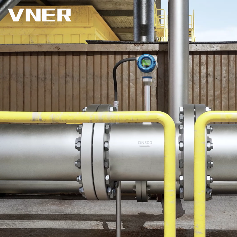 MA80T-TP Temperature and Pressure Compensated Vortex FlowmeterVortex flowmeter with RTD and pressure input for real-time density correction, mass and standard volume outputs in steam and compressed gas networks.View Product →
Swirl flow meters
Swirl meters, also called precession vortex meters, accelerate the flow through a helical path and detect the precession frequency of the swirling core. They offer a wider turndown ratio than standard vortex meters—often 30:1 or better—and are less sensitive to upstream disturbances. That makes them a strong choice for compressed air systems with variable demand, such as plants that run multiple shifts or have intermittent high-consumption equipment. VNER’s SA80T series swirl flow meter includes a temperature and pressure compensation option that corrects for density changes, which is useful when air temperature varies significantly between the compressor room and the point of use.
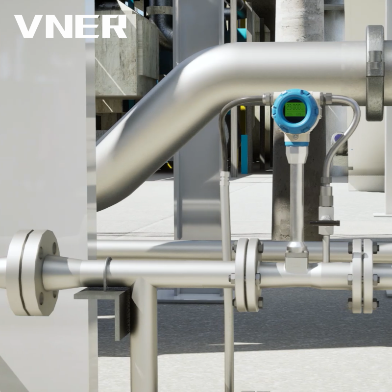 SA80T Series Swirl Flowmeter with Optional Temperature and Pressure CompensationSwirl/precession vortex flowmeter offering wide turndown and optional mass or standard volume output, suited to variable compressed air and steam measurement.View Product →
Coriolis mass flow meters
Coriolis meters measure mass flow directly by vibrating a tube and detecting the phase shift caused by the fluid’s inertia. They are the gold standard for accuracy, often within 0.1% to 0.5% of reading, and they measure mass flow, density, and temperature simultaneously. For compressed air, Coriolis meters are usually reserved for critical custody transfer, efficiency testing, or small-line applications where high accuracy justifies the higher cost. They cause almost no pressure drop and handle dirty or wet air better than thermal or vortex meters, but they are heavier and more expensive. VNER’s AC series and AG-CNG specialized Coriolis meters cover a range of line sizes, with the AG-CNG version tailored to compressed natural gas but also adaptable to other compressed gases.
Turbine flow meters
Turbine meters use a rotor that spins at a speed proportional to flow velocity. They are mechanically simple, cost-effective, and provide good accuracy for clean, dry gases. In compressed air service, turbine meters are often used for sub-metering individual departments or large pneumatic equipment. The rotor can be damaged by water slugs or particulate, so filtration and drying are essential. VNER’s LWQ series gas turbine flow meter is designed specifically for gas measurement and offers a reliable, repeatable solution for compressed air where the flow is relatively steady and clean.
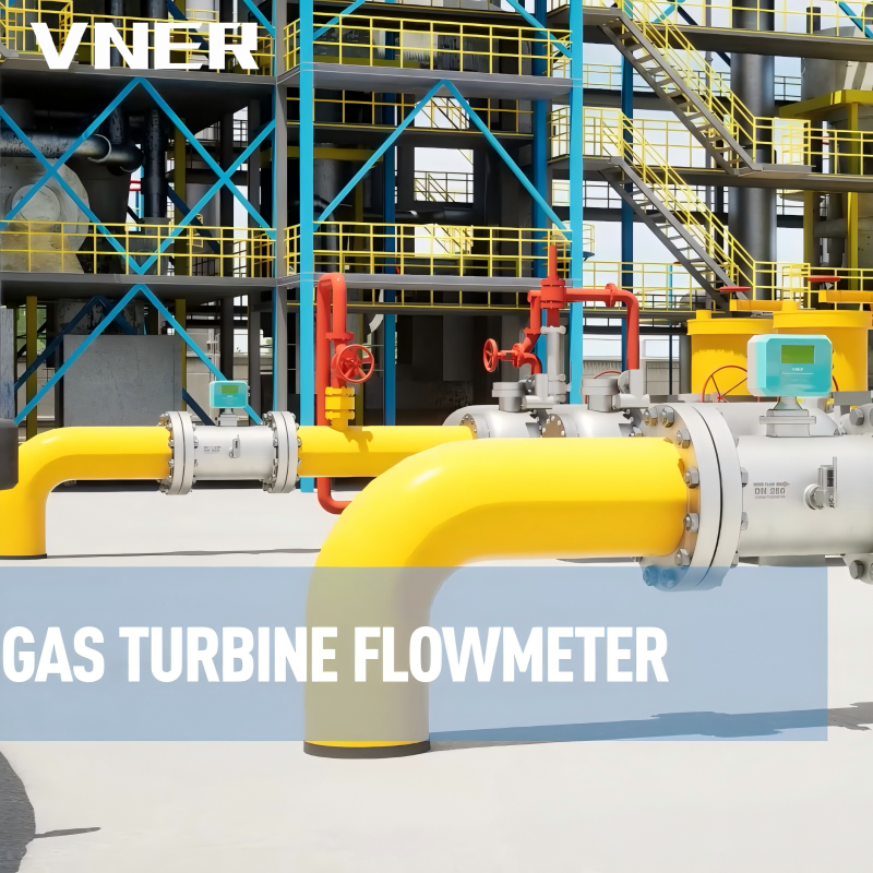 LWQ Series Gas Turbine Flowmeter for Clean Dry GasesGas turbine flowmeter with integrated temperature and pressure compensation for standard volume flow, used in compressed air sub-metering and steady clean gas applications.View Product →
Differential pressure flow meters
Differential pressure (DP) meters use an obstruction such as an orifice plate or averaging pitot tube to create a pressure drop that correlates with flow. They are inexpensive and well understood, but they have low turndown, high permanent pressure loss, and require temperature and pressure compensation for accurate mass flow. In compressed air systems, DP meters are sometimes used in large ducts or where a low-cost indication is sufficient, but they are rarely the best choice for energy management because of their limited range and pressure penalty.
Choosing the right flow meter for your compressed air system
With the technology options in mind, the next step is to match a meter to your specific site conditions. The decision comes down to eight practical factors: line size, flow range, accuracy requirement, air quality, pressure and temperature, turndown ratio, installation type, and total cost of ownership. The table below summarizes how the main technologies compare on these factors.
| Technology | Typical accuracy | Turndown | Best for | Main limitations |
|---|---|---|---|---|
| Thermal mass | ±2% of reading | 50:1 to 100:1 | Low-flow leak detection, insertion in large pipes | Sensitive to moisture and oil; needs clean, dry air |
| Vortex | ±1% of reading | 10:1 to 20:1 | Clean, dry air; medium to high flows | Pressure drop; minimum Reynolds number |
| Swirl | ±1% of reading | 30:1 | Variable demand; shorter straight runs | Wider turndown but still limited at very low flows |
| Coriolis | ±0.1% to 0.5% | 100:1 or better | Custody transfer, high accuracy, wet or dirty air | High cost; larger size and weight |
| Turbine | ±0.5% to 1% | 10:1 to 20:1 | Clean, dry air; sub-metering | Moving parts; sensitive to water slugs and particles |
| Differential pressure | ±1% to 2% full scale | 3:1 to 5:1 | Low-cost indication; large ducts | High pressure loss; needs compensation; low turndown |
Start with line size. Full-bore meters are available up to several inches, but above 4 inches, insertion-style meters become much more economical. For example, a 6-inch compressed air header with a thermal insertion meter can cost half as much as a full-bore vortex meter and still provide reliable mass flow. Next, define your flow range. If your system runs from a small weekend flow to a full production load, a 100:1 turndown thermal meter will capture both ends, while a vortex meter may drop out at the low end. Accuracy requirement follows use case: leak detection programs often work well with ±5% accuracy, but energy reporting for ISO 50001 may need ±2% or better. Air quality matters too. If your compressed air is not dried and filtered to instrument-quality levels, avoid thermal and turbine meters; consider Coriolis or a robust vortex design.
Pressure and temperature affect gas density. For volumetric meters such as vortex and turbine, you must compensate readings to standard conditions (e.g., scfm or Nm³/h). Many modern meters, including VNER’s SA80TTP and MA80T options, include integrated pressure and temperature sensors to output compensated mass flow directly. Turndown ratio determines how well the meter handles variable demand. Installation type—inline versus insertion—depends on pipe size, accessibility, and whether you can shut down the line. Finally, consider total cost of ownership: purchase price, installation cost, pressure drop energy cost, calibration interval, and expected service life. A cheaper meter that needs frequent calibration or causes significant pressure loss may cost more over five years than a premium alternative.
Installation best practices for compressed air flow meters
Even the best flow meter will underperform if installed poorly. Compressed air systems present specific challenges: pulsating flow from reciprocating compressors, vibration from nearby machinery, thermal gradients, and moisture that can condense in dead legs. Following these guidelines will help you get accurate, repeatable data from day one.
Straight pipe runs and flow conditioning
Most flow meters require a minimum upstream and downstream straight pipe length to ensure a fully developed, symmetrical velocity profile. For vortex and swirl meters, typical requirements are 10 to 15 pipe diameters upstream and 5 downstream. Thermal insertion meters often need 10 upstream and 5 downstream, but some designs tolerate shorter runs if they include flow conditioning. Coriolis meters are largely immune to upstream disturbances, which is one reason they are chosen for cramped retrofit spaces. Always check the manufacturer’s manual for exact figures; installing a meter too close to an elbow, valve, or reducer is a common cause of inaccurate readings.
Mounting orientation
Orientation affects drainage and sensor exposure. For thermal insertion meters in compressed air, install the probe from the side or top of the pipe to avoid condensate pooling on the sensors. Vortex meters can be mounted in any orientation, but vertical upward flow is preferred to prevent liquid accumulation around the bluff body. Coriolis meters should be installed so that the tubes drain naturally, especially in wet air service. Turbine meters generally require horizontal installation with the shaft horizontal to avoid bearing wear from gravity.
Vibration and pulsation
Reciprocating compressors create pulsating flow that can confuse vortex and turbine meters. If pulsation is significant, install a flow straightener or a pulsation dampener, or choose a Coriolis meter, which is less affected by pulsation. Vibration from nearby equipment can also cause false readings in vortex meters; mount the meter on a rigid support and use flexible conduit for signal cables. Thermal meters are relatively immune to vibration but can suffer from electrical noise if cables are routed near variable frequency drives.
Air quality and filtration
Compressed air often contains oil carryover, water vapor, and particulate. These contaminants can coat thermal sensors, erode turbine blades, or clog vortex bluff bodies. For critical measurement points, install a coalescing filter and a dryer upstream of the meter, and include a bypass for maintenance. If the air is particularly dirty, a Coriolis meter may be the only technology that survives without frequent cleaning.
Common pitfalls and how to avoid them
Field experience shows that most compressed air flow measurement problems trace back to a few avoidable mistakes. Being aware of them can save you weeks of troubleshooting and thousands of dollars in wasted energy.
Oversizing or undersizing the meter
A meter sized for peak flow will read poorly at low flows, and one sized for average flow will saturate during peak demand. Always size for the expected maximum flow with a 20% safety margin, but verify the turndown ratio covers your minimum flow. If your minimum flow is less than 5% of maximum, consider a dual-meter setup or a wide-turndown technology like thermal mass or Coriolis.
Ignoring pressure and temperature compensation
Compressed air volume changes with pressure and temperature. A vortex meter that reports actual cubic feet per minute (acfm) without compensation will show different “flow” numbers on a cold morning versus a hot afternoon, even if the mass of air is the same. Always convert to standard conditions (scfm or Nm³/h) for energy reporting and leak detection. Choose a meter with built-in pressure and temperature sensors, or add a separate transmitter and perform the math in your control system.
Neglecting calibration drift
All flow meters drift over time, but thermal mass meters are especially prone to drift when oil and moisture coat the sensors. Vortex and turbine meters can also shift if the bluff body or rotor wears. A simple annual verification using a portable clamp-on ultrasonic meter or a calibrated master meter can catch problems early. Some plants calibrate every two years and then wonder why their leak detection results seem inconsistent.
Poor data integration
A flow meter that outputs only a local display cannot feed energy dashboards or leak reports. Choose a meter with industry-standard outputs—4-20 mA, HART, Modbus, or pulse—and make sure your building automation or SCADA system can read them. Without integration, you are collecting data that nobody uses.
From audits to permanent monitoring: the ROI of continuous measurement
Many facilities start with a compressed air audit. A consultant brings a portable flow meter, measures a few points over a week, and delivers a report with leak estimates and savings recommendations. Audits are useful, but they capture only a snapshot. Compressed air demand changes with production schedules, season, and equipment maintenance. A leak that appears next month will go unnoticed until the next audit, which may be years away. Permanent monitoring turns that snapshot into a continuous feedback loop.
The return on investment for permanent flow monitoring typically comes from three sources. First, leak detection: continuous monitoring can identify abnormal flow patterns at night or on weekends when production is idle. A 100 hp compressor left running to feed a major leak can cost $30,000 per year. Second, energy optimization: with real-time flow data, you can adjust compressor sequencing, reduce pressure setpoints, and avoid artificial demand. Third, cost allocation: sub-metering departments or production lines encourages conservation and provides accurate data for internal billing. In many cases, the flow meter pays for itself within 6 to 18 months through energy savings alone.
For facilities pursuing ISO 50001 or corporate sustainability goals, permanent compressed air flow measurement is often a quick win. It provides verifiable data for energy performance indicators and demonstrates continuous improvement. VNER’s flow meters, including the MA80T vortex and SA80T swirl series, are designed for long-term industrial use and can be integrated into existing monitoring systems. You can learn more about the company’s engineering-driven approach on the VNER about page.
Maintenance and calibration essentials
Once a compressed air flow meter is installed and integrated, a modest maintenance routine keeps it accurate for years. The exact steps depend on the technology, but some principles apply across the board.
Visual inspections
Check the meter body and cable connections every three to six months. Look for signs of moisture intrusion, corrosion, or physical damage. For insertion meters, verify that the probe is still at the correct depth and that the compression fitting is tight. For vortex meters, inspect the bluff body for buildup or erosion. For turbine meters, listen for unusual noise that might indicate bearing wear.
Sensor cleaning
Thermal mass sensors should be cleaned according to the manufacturer’s instructions, typically with a soft brush and a compatible solvent. Never use abrasive materials that could damage the thin-film elements. Vortex and turbine meters generally need less frequent cleaning, but if you notice a gradual drop in reading accuracy, inspect the internal surfaces. Coriolis meters usually require no routine cleaning unless the process fluid is extremely dirty.
Calibration verification
Full recalibration in a flow lab is expensive and requires removing the meter from service. Instead, many plants use a portable clamp-on ultrasonic flow meter as a reference. Compare the permanent meter’s reading to the portable meter at three flow points: low, medium, and high. If the deviation exceeds your acceptable tolerance (often ±2% for energy management), schedule recalibration. Keep a log of these checks so you can spot drift trends over time.
Spare parts and documentation
Keep a spare sensor or probe on hand for critical meters, especially if lead times are long. Maintain a file with the meter’s model number, serial number, calibration certificate, and installation date. When you need technical support, having this information ready speeds up the process. VNER provides documentation and spare parts for its flow meter families, including the MA80T, SA80T, and LWQ series.
Final recommendations for compressed air flow measurement
Selecting an air flow meter for compressed air does not have to be overwhelming. Start by defining your primary goal: leak detection, energy reporting, cost allocation, or custody transfer. That goal sets your accuracy and turndown requirements. Then evaluate your pipe size, air quality, and installation constraints. For most industrial plants, a thermal mass insertion meter or a vortex meter will deliver the best balance of cost and performance. If you have variable demand and shorter straight runs, a swirl meter like the SA80T is a strong contender. For the highest accuracy or wet, dirty air, choose a Coriolis meter. Turbine meters are cost-effective for clean, dry sub-metering.
Whichever technology you choose, install it correctly, compensate for pressure and temperature, and integrate the data into your energy management system. Verify calibration annually with a portable reference. And remember that flow measurement is not a one-time project; it is an ongoing practice that keeps your compressed air system efficient, reliable, and transparent. As industrial automation continues to adopt more sensors, compressed air flow data will become as standard as pressure and temperature. The plants that start measuring now will have a head start on savings. For more background on how flow sensors are increasingly used in industrial automation, see this industry news article.


Products
Contact Information
-

+86 18652789521
+86-0514-83633600 / 83633900 -

+86-0514-83633600 / 83633900
-

s@vner.com.cn
katherine@vner.com.cn -

No. 11 Xingye Road, Chenji Town Industrial Park, Yizheng, Yangzhou, China
