
 0
0
 EN
EN  English
 عربى
عربى Español
 русский
If you need any help, please feel free to contact us
Home / News / Industry News / Flow Meter Calibration: Methods, Tolerances, Traceability, and Recalibration Cycles
Flow Meter Calibration: Methods, Tolerances, Traceability, and Recalibration Cycles
The conversation usually starts the same way. A plant engineer has a discrepancy on the desk: the billing meter reads 0.7% below the receiving meter, or the mass balance on a batch reactor drifts by half a percent across a shift, and someone in the meeting says the word "calibration." Before anybody loosens a flange, it is worth deciding what you are actually asking for. A calibration certificate will not fix a meter sitting six diameters downstream of a double elbow, and it will not fix a control valve cavitating through the same pipe run.
Here is the short answer this article builds on: flow meter calibration is a measurement comparison against a traceable reference, carried out under defined conditions, with a stated uncertainty. It is not a repair, not a firmware reset, and not a guarantee that the meter will read correctly once it is back in your line. If you want the number on the transmitter to match the number on the invoice, you need three things in the right order: a physically sound installation, a calibration you can trace, and an honest assessment of how much the meter drifts between services. Everything else is detail, and the detail is where most calibration budgets get wasted.
What a Calibration Certificate Really Certifies
A certificate is a claim about a comparison, not a promise about your process. That distinction matters when you are standing in front of a meter that has just come back from a laboratory with a clean sheet, yet still reads wrong on site.
Calibration, verification, and adjustment are three different jobs
Verification means you compare the meter against a reference and record the difference without changing anything. Adjustment means you change the meter's scaling, K-factor, or zero point so its output matches the reference. Calibration is the broader activity that produces a documented comparison with an uncertainty statement, and it may or may not include adjustment. When you send a meter out, ask which of the three you are buying. An "as-found" record before adjustment is the single most valuable piece of data you will get, because it tells you the real drift rate of that meter in your service. If the laboratory adjusts first and reports only the as-left result, you have paid for a clean number and learned nothing.
Traceability is a chain, not a logo
Traceable means every reference in the chain links back to a national or international standard through an unbroken series of documented comparisons, each with its own uncertainty. In practice you should expect an ISO/IEC 17025 accredited laboratory, an uncertainty budget prepared along the lines of the GUM, and results reported at a coverage factor of k=2, which corresponds to roughly 95% confidence. A certificate stating only that a meter was "calibrated" and "within specification," with no reference identification, no uncertainty, and no environmental conditions, is a data sheet rather than a calibration record. It will not survive a customer audit and it will not help you when a discrepancy turns into a commercial argument.
The useful output is a table of points: normally five, at something like 10%, 25%, 50%, 75%, and 100% of the meter's range, often run ascending and descending, with repeat runs to establish repeatability. Four or five repeat points at the same flow rate tell you far more about a meter's noise floor than a single sweep ever will.
The Laboratory Methods You Will Actually Be Quoted
Every calibration house has a favourite rig, and which one you get quoted usually depends on your line size, your fluid, and how much downtime you can tolerate. The methods below cover the overwhelming majority of industrial work.
Gravimetric, or weighing method
Liquid passes through the meter under test and is collected in a weigh tank sitting on a load cell or a precision scale. Mass is converted to volume using density at the measured temperature. There is no intermediate reference volume to erode or deform, which is why gravimetric rigs sit at the top of the accuracy ladder for liquids, typically 0.05% to 0.10%. The practical limits are size and time: weigh tanks constrain the maximum flow rate, and each point needs the system to settle, divert, and drain cleanly. Wetting and drainage errors are the classic gremlins, and a good laboratory will have a documented drain-and-wait procedure.
Volumetric method
Here the liquid fills a calibrated tank or passes through a calibrated volumetric vessel, and the level is read by a sight glass, float, or servo gauge. It is simpler and cheaper than gravimetric work, but the tank wall, the level reading, and the drainage film on the walls dominate the uncertainty, which typically lands between 0.10% and 0.25%. Volumetric proving remains a workhorse for general industrial meters where a fraction of a percent is enough.
Master meter comparison
A previously calibrated reference meter is mounted in series upstream of the unit under test, and both readings are compared at the same time. This is the only practical method for very large lines, high flow rates, and for gas work. The rule of thumb is a test uncertainty ratio: the reference should be four to ten times more accurate than the meter being tested, or the comparison tells you less than you think. A Coriolis meter is the most common transfer standard nowadays because it measures mass directly, holds its zero well, and covers a wide turndown in a single device.
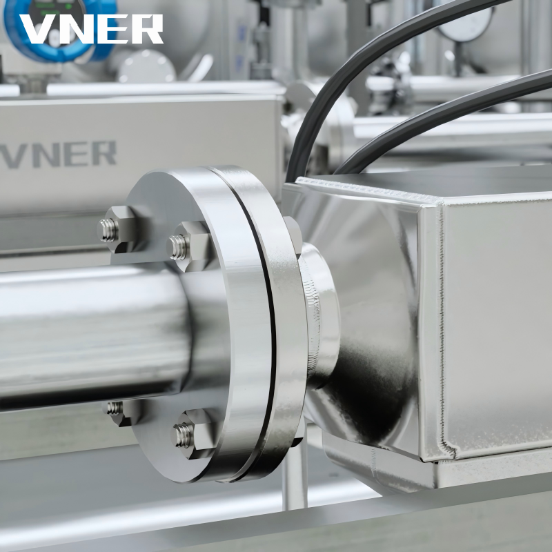 AC Series Coriolis Mass Flowmeter for Mass, Density, and Temperature MeasurementA Coriolis transfer standard for direct mass, density, and temperature measurement, suited to high-flow, large-line, gas, and multiphase comparisons.View Product →
Piston provers and pipe provers
A piston displaces a known volume through a calibrated cylinder, and the pulses from the meter are counted against that volume. Pipe provers do the same job on a larger scale for liquid hydrocarbon custody transfer. Uncertainties of 0.05% to 0.10% are achievable, but the displaced volume is small, so you need repeat runs at a stable flow rate rather than one long sweep. These rigs are the backbone of petroleum metering stations.
Gas rigs: sonic nozzles, bell provers, and PVTt systems
Gas is harder. Bell provers dominate low flows, critical-flow venturi nozzles cover the middle, and gravimetric or pressure-volume-temperature-time systems are used where the highest accuracy is required. Uncertainty ranges from roughly 0.15% up to several tenths of a percent. Most industrial gas meters are tested on air, and that decision shapes everything discussed in the next section.
| Method | Typical uncertainty (k=2) | Best suited to | Practical limits |
|---|---|---|---|
| Gravimetric (weighing) | 0.05% – 0.10% | Liquids, small to medium lines, high-value metering | Weigh-tank size caps flow rate, long settling and drain times |
| Volumetric (calibrated tank) | 0.10% – 0.25% | General industrial liquid meters | Wall effects, level reading, and wetting dominate the budget |
| Master meter comparison | 0.10% – 0.25% | Large meters, high flows, gases | Reference must be four to ten times better than the unit under test |
| Piston or pipe prover | 0.05% – 0.10% | Liquid hydrocarbon custody transfer | Small displaced volume, needs repeat runs and steady flow |
| Sonic nozzle or bell prover | 0.15% – 0.50% | Gas meters on air or natural gas | Reynolds number matching, air properties differ from process gas |
Liquid and Gas Calibration Are Not the Same Problem
People new to metering often assume a calibration is a calibration. It is not. Liquid work is mostly a volume problem; gas work is mostly a density, viscosity, and Reynolds number problem, and the two demand different rigs, different skills, and different conversations with your supplier.
Liquids: weighing is the gold standard, and temperature is the enemy
For liquids, the chain from mass to volume runs through density, and density moves with temperature. A tenth of a degree of unmeasured temperature error in a hydrocarbon stream can shift the calculated volume by more than the calibration itself. Good laboratories measure liquid temperature at the meter and at the collection vessel, and they document how long the system was allowed to stabilise. If your process fluid is viscous, non-conductive, or heavily aerated, tell the laboratory in advance. Entrained air is the most common cause of a "failed" calibration that is actually a bad test setup, and it shows up as erratic readings rather than a consistent offset.
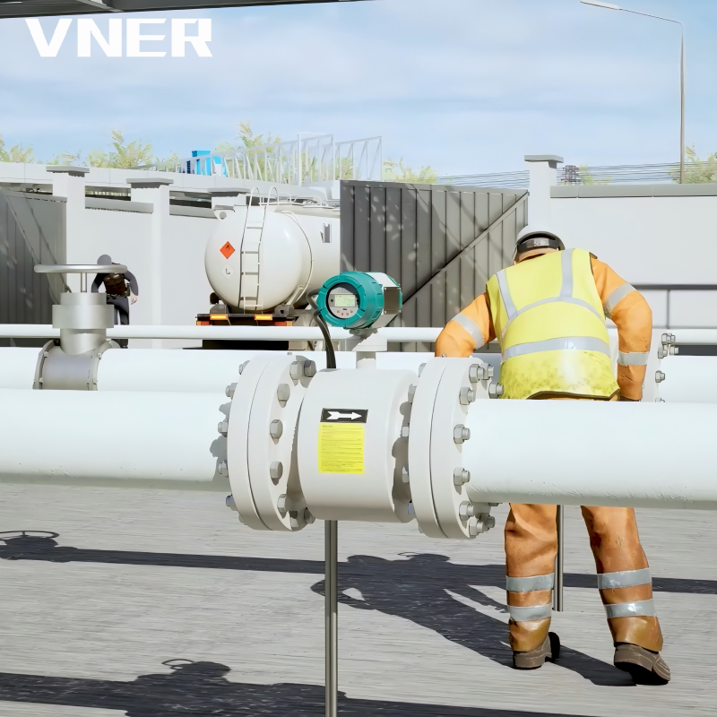 LDG Economy General-Purpose Electromagnetic Flowmeter for Conductive LiquidsA cost-effective electromagnetic flowmeter for conductive liquids and slurries, with no moving parts and negligible pressure loss in water, chemical, and mining duties.View Product →
Electromagnetic meters add their own wrinkle: they are calibrated on water, but they operate on whatever conductive liquid the plant sends through them. For most conductive liquids the flow profile dominates and the fluid itself contributes little, which is why a clean water calibration is a defensible starting point. If you want to see how that principle is applied in a production instrument, the design notes behind LDG electromagnetic flow meters are a useful read, particularly the discussion of lining choice and grounding.
Gas: air is usually a stand-in, and that matters
Testing a natural gas meter on air is convenient and inexpensive, but air and methane differ in density, viscosity, and compressibility. If the test is run at a Reynolds number close to the operating condition, the extrapolation error is small. If the laboratory simply opens a valve and lets air through at whatever pressure the shop supply provides, the meter may be checked far outside its real operating regime, and the K-factor you take away can be wrong by several tenths of a percent. Ask the laboratory to report the Reynolds number at each test point, plus the gas temperature and pressure. If they cannot, they are not testing your application, they are testing their rig.
Tolerances, Uncertainty, and the Four-to-One Rule
Specifying "±0.5%" in a purchase order is only half a specification. You also need to say at what flow range that figure holds, at what Reynolds number, over what fluid, and with what upstream piping. A vortex meter rated at ±1% of reading typically only holds that from about 20:1 turndown upward, because below a certain Reynolds number the shedding frequency becomes unstable and the meter simply stops being a meter.
The second half of the specification is the test uncertainty ratio. If your meter's permitted error is 0.5% and the calibration rig's uncertainty is 0.4%, then a passing result proves very little. The conventional target is 4:1, meaning the rig should be four times better than the tolerance it is judging. Where that is impossible, for example on a very large gas meter, the certificate should state the rig uncertainty openly so that you can decide how much of the observed error is real drift and how much is measurement noise.
In contracts, tie calibration to a method and an accreditation rather than to a number. "Calibrated gravimetrically by an ISO/IEC 17025 accredited laboratory, five points ascending and descending, three repeats, uncertainty reported at k=2 and not exceeding one quarter of the meter's maximum permissible error" is a sentence that prevents arguments. "Calibrated" alone does not.
In-Situ Verification versus Sending the Meter to a Laboratory
The decision is usually driven by line size, fluid hazard, and downtime cost. Small meters come out easily and ship cheaply. A DN300 electromagnetic meter on a buried water main is a different proposition entirely.
When to take the meter to a bench
Bench calibration gives you a controlled fluid, stable temperature, a known reference, and a repeatable test. It is the only way to establish a defensible baseline, and it is what you want for custody transfer, fiscal metering, and any application where a regulatory body expects an accredited certificate. It is also the right choice when you suspect mechanical damage: a bent turbine rotor or a damaged Coriolis tube cannot be diagnosed in the line.
When in-situ verification is good enough
Field verification, using a clamp-on ultrasonic meter as a check device, a portable prover, or a tracer method on very large pipes, does not replace a laboratory calibration. What it does extremely well is answer a narrower question: has the meter moved since the last known-good baseline? A repeatable field check, performed the same way each time, gives you a trend. Trends catch drift. A single field check is a snapshot and should never be used to declare a meter accurate, only to decide whether it needs to come out.
Two practical rules make field verification worth the effort. First, always use the same reference device and the same test points, so that the comparison is apples to apples. Second, record the conditions — flow rate, temperature, and any valving change — because a clamp-on reading taken at half the normal flow rate is not comparable with one taken at design flow.
How Often Should a Flow Meter Be Recalibrated?
Manufacturers quote intervals, regulators mandate them for trade, and both are starting points rather than answers. The honest answer is that the first recalibration should be a diagnostic exercise: pull the as-found data and see how much the meter moved. If it moved 0.1% in two years in a clean fluid, you can extend the interval. If it moved 0.8% in twelve months, you have a process problem or the wrong meter.
| Application | Typical starting interval | Main driver |
|---|---|---|
| Liquid hydrocarbon custody transfer | 12 months | Contractual and regulatory requirements |
| Fiscal or billing gas metering | 12 months | Regulatory approval conditions and revenue exposure |
| General process control (electromagnetic, vortex, Coriolis) | 24 – 36 months | Observed drift, product value, cost of a bad batch |
| Water and wastewater | 36 – 60 months | Low revenue sensitivity, stable clean-fluid service |
| Compressed natural gas dispensing | 12 months | Trade measurement rules and high cycle counts |
| Environmental or permit-driven monitoring | Per permit | Regulator-defined, not risk-based |
Two factors should shorten any interval. The first is a dirty service: slurries, polymer dosing, and streams that coat electrodes will change a meter's behaviour long before the electronics drift. The second is criticality: if the meter is the only barrier between you and an off-spec shipment, the cost of a mid-year verification is trivial compared with the cost of being wrong.
Meter-by-Meter Notes
Different measuring principles fail in different ways, and knowing what to look for saves a lot of unnecessary shipping.
Electromagnetic meters
The electronics rarely drift. What changes is the electrode surface, the liner, and the grounding path. A thin insulating film on the electrodes can shift the reading by several percent with no error code. Ask for a zero check under full, still pipe conditions before anything is disconnected.
Coriolis meters
Mass flow is close to a primary measurement, so a Coriolis meter is unusually stable — provided it is zeroed properly. Pressure effects on tube stiffness are real, on the order of a tenth of a percent per ten bar in some designs, so verify at or near operating pressure where the value justifies it. Always re-zero after installation and after any significant piping change.
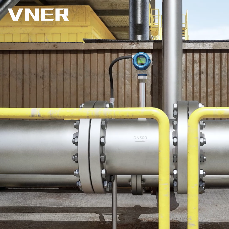 MA80T-TP Temperature/Pressure Compensated Vortex Flowmeter for Steam and GasA compensated vortex flowmeter for steam and gas, where temperature and pressure correction, Reynolds-range calibration, and bluff-body fouling affect frequency-based measurement.View Product →
Vortex and swirl meters
These are frequency devices, and the K-factor changes with Reynolds number. A laboratory calibration on water is valid only within a stated Reynolds range. In the field, the bluff body picks up fibres, scale, and process debris, and the first symptom is usually a low reading at low flow, which is easy to confuse with drift.
Turbine meters
Bearings wear, and wear shows up as a slowly falling K-factor. Keep a plot of K-factor against service hours; the slope tells you the maintenance interval far more reliably than any calendar.
Ultrasonic meters
Performance depends on path geometry and transducer condition. Clamp-on units are effectively impossible to calibrate to custody-transfer accuracy because the acoustic path depends on the pipe and the installation. Inline multipath meters are calibrated on a flow rig, and their diagnostics will usually flag a failing transducer before the flow reading degrades.
Thermal mass meters
They measure mass flow via heat transfer, so the result depends on gas composition and specific heat. If the gas mix changes, the calibration is no longer valid, and no amount of laboratory work will fix that.
Installation Effects That Invalidate a Perfect Calibration
This is the part most often skipped, and it is where the money goes. A meter calibrated to 0.1% in a laboratory and installed with six diameters of straight pipe after a double elbow will carry an installation error of one percent or more, and no certificate will mention it.
- Insufficient straight length upstream and downstream, particularly after two elbows out of plane, which generate swirl that survives for many diameters.
- Gasket protrusion or a weld bead sitting in the bore, creating a local velocity distortion right at the sensing plane.
- Control valves downstream instead of upstream, producing flashing or cavitation inside the meter body.
- Partially full pipes in liquid service, which is the classic cause of a reading that wanders with no flow change.
- Entrained air or gas pockets after a pump suction, showing up as noise rather than a bias.
- Variable frequency drives and inadequate grounding, which couple noise into electromagnetic and Coriolis signal cables.
- Pulsating flow from reciprocating pumps or compressors, which can bias vortex and turbine readings dramatically.
Before you spend money on a recalibration, spend an hour with the installation drawing and the last three months of trend data. If the error appears suddenly and correlates with a process change, the meter is probably telling the truth and the process has moved.
Documentation and What an Auditor Will Ask For
If your calibration records are ever examined, the questions are predictable and fairly narrow. Which laboratory performed the work, and under what accreditation? What reference was used, and what is its own traceability? What method was applied, and at what flow points? What were the environmental conditions and the fluid? What was the as-found result, what adjustment was made, and what was the as-left result? What is the uncertainty at k=2?
Keep the original certificates, not scans with the tables cropped out. Keep the as-found data even for meters that passed. And keep a simple trend file per instrument: date, service, as-found error at the mid-range point, and any adjustment applied. Ten years of that file is worth more than any single certificate, because it converts calibration from a recurring expense into a predictive maintenance input.
Between Calibrations: Diagnostics and Field Checks
Modern transmitters give you more verification material than most plants use. Empty-pipe detection, electrode impedance, coil resistance, zero stability, and signal-to-noise ratio are all reported continuously by many electromagnetic and Coriolis instruments. Trend them. A slowly rising electrode impedance is a coating problem building, and it will show up in the diagnostics weeks before it shows up in the flow reading.
Three field habits pay for themselves. First, record the zero and the raw frequency or pulse output at a stable operating condition once a month, and compare it with the baseline. Second, check the grounding and cable shielding whenever electrical work has been done nearby. Third, verify the meter at a single point during a planned shutdown when a portable reference is available, and log the result whether it is good or bad. A verification that only gets recorded when it passes is not a verification programme.
Choosing a Supplier Whose Calibration You Can Rely On
The instrument and the calibration service should be considered together, because a supplier who understands both will tell you when a recalibration is not the answer. A meter manufacturer with its own flow rigs has an advantage: they know the K-factor history of their own designs, they can tell you what typically drifts and what does not, and they can often shorten the loop between a field problem and a bench test.
VNER, the brand behind Jiangsu Vner Electronic Technology, has been building flow instruments since 2011 across electromagnetic, Coriolis, vortex, swirl, and turbine lines, with in-house calibration and certified quality processes supporting deliveries into more than thirty countries. That combination matters mainly in one practical way: when a meter comes back with an unexpected as-found error, the people who built it can usually say within a day whether the cause is the instrument, the installation, or the process. Their manufacturing and calibration facilities are described in more detail if you want to see how the engineering-driven sizing process works in practice.
Whoever you buy from, ask five questions before signing: which accredited laboratory performs the calibration; what uncertainty is quoted and at what coverage factor; whether as-found data is reported before adjustment; how the test Reynolds number is matched to your process; and what interval they recommend for your specific fluid, not for their catalogue. Suppliers who answer all five comfortably are usually the ones whose meters stay in specification.
Calibration is a comparison, and like any comparison it is only as good as the reference, the conditions, and the honesty of the record. Get the installation right first, specify the method and uncertainty rather than a bare percentage, insist on as-found data, and treat the first recalibration as a measurement of drift rather than a rubber stamp. Do that, and the next discrepancy meeting will be short: you will know whether the meter moved, by how much, and why.
The meter that reads correctly for a decade is rarely the one that was calibrated most often. It is the one that was specified for the fluid, installed with enough straight length, and checked on a schedule built from its own history.


Products
Contact Information
-

+86 18652789521
+86-0514-83633600 / 83633900 -

+86-0514-83633600 / 83633900
-

s@vner.com.cn
katherine@vner.com.cn -

No. 11 Xingye Road, Chenji Town Industrial Park, Yizheng, Yangzhou, China
