
 0
 EN
 English
 عربى
 Español
 русский
If you need any help, please feel free to contact us
Home / News / Industry News / How Does a Pressure Transducer Work? Sensing, Signal Conditioning, and Field Selection
How Does a Pressure Transducer Work? Sensing, Signal Conditioning, and Field Selection
A technician sees 12.0 mA on a pressure loop, but the control room display does not match the expected tank head. The transmitter is powered, the wiring is clean, and the calibration certificate is only six months old. The problem is often not the electronics at all. It may be a gauge-versus-absolute reference error, a blocked impulse line, a diaphragm exposed to the wrong medium, or a zero shift caused by mounting stress. Understanding how a pressure transducer works makes those failures easier to separate from normal process variation.
The short answer is that a pressure transducer converts pressure into an electrical signal through a mechanical sensing element and a signal-conditioning circuit. Pressure enters a process connection, deflects an isolation diaphragm or sensing diaphragm, and changes a resistance, capacitance, or charge output. The circuit linearizes that change and produces a standard signal such as 4-20 mA, 0-5 V, or a digital protocol. The useful accuracy depends less on the marketing headline than on reference type, temperature compensation, overpressure protection, installation, and long-term stability.
The Short Answer: Pressure Becomes an Electrical Signal
A pressure transducer has three practical stages: a pressure port, a sensing element, and an output stage. The pressure port isolates the process fluid from the electronics. In a common industrial design, a stainless-steel isolation diaphragm separates the process medium from a filled chamber. That fill fluid transfers pressure to a silicon sensing diaphragm. As the sensing diaphragm deflects, piezoresistive strain gauges or a capacitive electrode pair produce a small electrical change. The electronics then amplify, linearize, and temperature-compensate that change.
The reference pressure matters as much as the sensor. A gauge transducer measures pressure relative to local atmosphere. An absolute transducer measures relative to a sealed vacuum. A differential transducer measures the difference between two pressure ports. A sealed-gauge unit uses a sealed reference that is not truly absolute. If a specification says 0-10 bar but does not state gauge, absolute, or differential, the reading may be wrong by roughly one atmosphere, or by the local barometric pressure at the plant. For low-pressure tanks and gas lines, that difference is not a minor detail.
Output type also shapes the installation. A two-wire 4-20 mA loop carries power and signal on the same pair. A three-wire voltage unit needs a stable supply and short signal runs. A digital or HART-enabled unit can report secondary variables such as sensor temperature and can support remote zeroing. In a plant with long cable runs and electrical noise, the 4-20 mA loop remains common because a current signal is less sensitive to voltage drop than a low-level voltage output.
Common Pressure Transducer Technologies and Where They Fit
Most industrial transducers use one of a few sensing principles. The principle determines whether the device is suitable for static pressure, fast pressure pulsation, high overpressure, hygienic service, or a compact manifold installation. The table below is a practical comparison rather than a ranking.
| Technology | How it senses pressure | Strengths | Limits | Typical fit |
|---|---|---|---|---|
| Piezoresistive silicon | Strain gauges diffused into a silicon diaphragm change resistance as pressure deflects the diaphragm. | Compact, low cost, good linearity, suitable for many static and dynamic duties. | Temperature sensitivity; needs compensation; limited resistance to aggressive media without isolation. | General process pressure, air and gas lines, OEM equipment, differential pressure modules. |
| Capacitive | Diaphragm movement changes the gap between electrodes and therefore capacitance. | Good low-pressure sensitivity, low hysteresis, stable zero in many designs. | More sensitive to assembly tolerances and condensation; often larger than silicon strain-gauge units. | Low differential pressure, clean gas, HVAC and laboratory flow elements. |
| Piezoelectric | Pressure applied to a crystal or ceramic generates charge. | Fast response, high frequency, good for pulsation and blast pressure. | Cannot measure true static pressure for long periods; charge leakage affects low-frequency response. | Dynamic pressure, combustion, water hammer, test stands. |
| Bonded foil strain gauge | A foil gauge bonded to a metal diaphragm or beam changes resistance with strain. | Rugged, high-pressure capability, familiar signal conditioning. | Lower sensitivity than silicon; larger size; installation and bonding quality matter. | Heavy industrial pressure, hydraulic systems, high-overpressure service. |
| Variable inductance or LVDT | A magnetic core moves with a diaphragm and changes coupling between coils. | Robust at high pressure, good resistance to harsh environments, strong output. | Bulkier, higher power, more complex electronics. | Power plant systems, high-pressure oil and gas duties, legacy plant replacements. |
What the Datasheet Does Not Tell You: Accuracy, Turndown, and Drift
Accuracy is often written as a percentage of full scale or a percentage of span. Those are not the same when a transmitter is used at low pressure. A 0.5% full-scale unit on a 0-100 bar range has a headline error of 0.5 bar. If the actual working point is 5 bar, that error is 10% of the reading. A 0.1% full-scale unit on a 0-10 bar range has an error of 0.01 bar, which is far better for low-pressure service. The range should be chosen for the working pressure, not for the largest pressure the plant might ever see, unless overpressure protection is specified separately.
Thermal effects are equally important. A datasheet may state 0.02% full scale per degree Celsius for zero shift and 0.02% of reading for span shift. On a 10 bar range, a 20 degrees Celsius change from calibration temperature can produce a zero shift of 0.04 bar. That matters on a low-pressure gas line or a level application. Long-term stability, typically stated as a percentage of span per year, also affects calibration intervals. In custody transfer or energy accounting, an apparently small drift can change billing or efficiency calculations.
Check proof pressure and burst pressure before ordering. Proof pressure is the pressure the unit can survive without a permanent shift in calibration. Burst pressure is a safety limit, not an operating limit. Also check the wetted materials: 316L stainless steel is common, but chloride service, seawater, ammonia, and hygienic processes may require duplex steel, Hastelloy, titanium, PTFE faces, or a remote seal. A transducer that is accurate in air may fail quickly in a corrosive liquid if the diaphragm and process connection are not matched to the medium.
Pressure Transducers in Flow Measurement and Compensation
Flow measurement is one of the most common reasons to install a pressure transducer. A vortex, orifice, turbine, or swirl meter measures a volumetric or velocity-related quantity, but gas density changes with static pressure and temperature. Without pressure compensation, a gas flow reading can drift simply because the line pressure changed during the shift. A pressure transducer supplies the line pressure input; a temperature sensor supplies the thermal input; the flow computer converts the measured volume to standard conditions or mass flow.
For differential-pressure flow elements, two pressure ports are needed, and the transmitter measures the pressure difference across the element. For vortex and swirl meters, a single static pressure input is often enough when the meter coefficient and gas properties are known. The pressure transducer does not have to be the most accurate instrument in the plant, but its range, reference type, and response time must match the flow calculation. A slow pressure transducer on a fast gas header can introduce a lag that is visible in flow totalization.
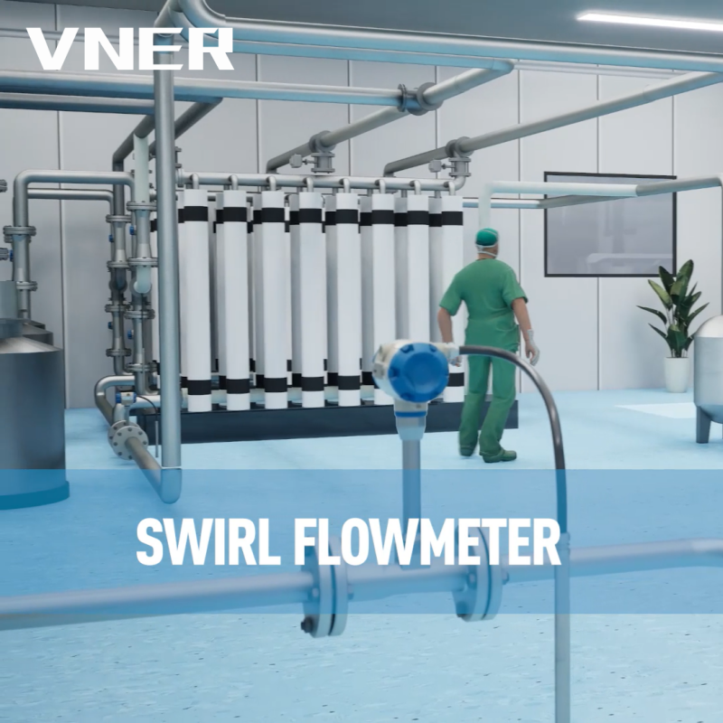 SA80T-TP Temperature and Pressure Compensated Swirl FlowmeterIntegrates temperature and pressure measurement for real-time density correction and mass or standard-volume flow output in steam and gas metering.View Product →
In packaged flow metering, the pressure and temperature inputs are sometimes integrated into the flowmeter or its companion computer. VNER’s SA80TTP series is an example of a temperature-pressure-compensated swirl flowmeter intended for service where line conditions change. The same engineering logic applies to other meter families: the pressure input is only useful if the compensation calculation, the pressure range, and the process connection are selected together. For a deeper technical view, see this guide to pressure and temperature compensation for vortex flowmeters.
In liquid service, pressure compensation is less often about density and more often about safety, pump protection, or confirming that the line is above vapor pressure. A pressure transducer upstream of a control valve can reveal cavitation risk. A pressure transmitter on a filter can show loading before flow drops. In these cases, the transducer is a diagnostic input rather than a custody-transfer measurement, so a lower-cost gauge unit with a suitable overpressure rating may be adequate.
Installation Details That Decide Whether the Reading Is Trustworthy
Most pressure-transducer problems begin before the electronics are powered. The tap location, impulse line, and mounting method determine what pressure actually reaches the diaphragm. For gas service, mount the tap on the top or side of the pipe so condensate does not collect in the impulse line. For liquid service, mount the tap on the side or bottom and arrange the impulse line to vent gas pockets. For steam, use a condensate pot or a pigtail siphon so live steam does not reach the diaphragm directly.
Use a manifold with an isolation valve and a vent or drain valve. A direct-mounted transmitter on a vibrating skid may need remote mounting with a capillary or a flexible impulse line. Tighten the process connection to the specified torque; over-torquing can distort the diaphragm and shift the zero. Avoid installing a gauge transducer in a location where the local atmospheric pressure is not representative of the process reference, such as a pressurized enclosure or a sealed cabinet.
Electrical installation deserves the same care. Use shielded twisted-pair cable for low-level or 4-20 mA signals, ground the shield at one end, and keep the cable away from variable-frequency drives and motor cables. Check loop load against the supply voltage. A 24 V supply may not drive a 4-20 mA loop through a 500 ohm input if the transmitter needs a minimum 12 V at its terminals. For hazardous areas, confirm the intrinsic safety barrier or isolator rating, cable capacitance, and entity parameters before commissioning.
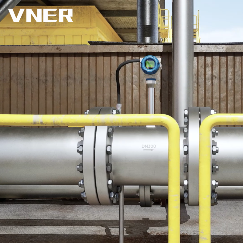 MA80T-TP Temperature and Pressure Compensated Vortex FlowmeterCombines Kármán vortex sensing with integrated temperature and pressure inputs to calculate compensated volumetric, standard, and mass flow for steam and gas networks.View Product →
In flow applications, the pressure transducer is often part of a meter package. VNER’s MA80T vortex flowmeter series, for example, is selected with process conditions and compensation requirements in mind rather than as a standalone catalog item. That matters when the pressure input is used to correct gas density; a small error in the pressure reference can become a systematic error in the flow total.
Selection Checklist for Industrial Buyers
Before requesting a quotation, define the process and the measurement purpose. A pressure transducer for a local gauge display has different requirements from one used in a safety interlock or a flow computer. The following checklist prevents most specification gaps.
- Pressure type: gauge, absolute, differential, or sealed gauge. State the reference explicitly.
- Working range and overpressure: normal operating pressure, maximum pressure, proof pressure, and expected pressure spikes.
- Process medium: liquid, gas, steam, slurry, food product, or corrosive chemical. List wetted materials and required surface finish.
- Accuracy: percent of span or reading, including thermal zero and span effects at the actual installation temperature.
- Output and power: 4-20 mA, voltage, HART, Modbus, or another protocol; two-wire or three-wire; supply voltage and loop load.
- Process connection and mounting: thread, flange, hygienic clamp, remote seal, capillary length, and manifold requirements.
- Environment: ambient temperature, vibration, humidity, ingress protection, washdown, and hazardous-area classification.
- Calibration and documentation: traceability, test certificate, material certificates, and recommended recalibration interval.
For projects involving EPC contractors, terminal users, and OEM equipment builders, the interface between the transducer and the flow computer deserves a separate check. Confirm the pressure unit, the reference type, the damping setting, and the fail-safe output. A 4-20 mA signal that reads 3.8 mA may mean a zero fault, a wiring problem, or a saturated sensor. The receiver should be configured to match the transmitter’s selected range and alarm behavior.
Troubleshooting a Pressure Transducer in the Field
Start with the physical installation before adjusting the electronics. A zero that changes after a pump starts often points to mounting stress, vibration, or a liquid-filled impulse line with trapped air. A reading that is high and slow to respond may come from a blocked tap or a clogged diaphragm seal. A reading that is low and noisy may come from a partially open vent valve or a loose connection.
- No output: check loop power, polarity, fuse, barrier, and terminal voltage at the transmitter.
- Zero shift: vent the manifold, equalize the ports, check mounting torque, and confirm the reference type.
- Erratic signal: inspect grounding, shielding, cable routing, moisture ingress, and vibration at the transmitter.
- Slow response: check impulse-line blockage, fill-fluid viscosity, diaphragm coating, and damping configuration.
- Drift over time: compare against a traceable gauge, review temperature history, and inspect the diaphragm for corrosion or deformation.
Do not use a pressure transducer as a mechanical stop. If the process can exceed the proof pressure during a upset, add a snubber, a surge protector, a manifold, or a higher-rated transmitter. For sanitary and slurry processes, a flush-mounted diaphragm or a remote seal can prevent a dead-end cavity from clogging. For steam, verify that the condensate pot is filled and that the impulse line slopes correctly.
What to Verify Before You Specify
A pressure transducer works by turning a mechanical deflection into a conditioned electrical signal, but the measurement is only as good as the reference, range, materials, and installation. The key questions are not only “what accuracy?” but also “accuracy at what pressure, in what temperature range, with what reference, and against what overpressure?” Answer those questions first, and the electronics selection becomes much simpler.
VNER’s role in flow measurement is closely tied to this system view. The company’s engineering-driven sizing and selection approach treats pressure and temperature inputs as part of the flow measurement package, not as accessories added after the meter is chosen. Whether the application is natural gas, water, petrochemical service, or a packaged skid, the pressure transducer should be selected with the same care as the flow element it supports.


Products
Contact Information
-

+86 18652789521
+86-0514-83633600 / 83633900 -

+86-0514-83633600 / 83633900
-

s@vner.com.cn
katherine@vner.com.cn -

No. 11 Xingye Road, Chenji Town Industrial Park, Yizheng, Yangzhou, China
