 English
 عربى
عربى Español
 русский
If you need any help, please feel free to contact us
Vortex Flowmeter Guide: Pressure & Temperature Compensation
A vortex flowmeter measures volumetric flow by detecting the frequency of vortices shed by a bluff body placed in the flow stream — a principle known as the von Kármán effect. For applications involving steam, compressed gas, or any fluid where density changes significantly with operating conditions, a standard vortex flowmeter is insufficient on its own. Pressure compensation and temperature compensation variants integrate additional sensors directly into the meter body to calculate mass flow or corrected volumetric flow in real time, eliminating the need for external instrumentation and manual correction calculations. Choosing the right configuration depends on your fluid type, required accuracy, and whether pressure, temperature, or both vary during normal operation.
How a Vortex Flowmeter Works
The operating principle of a vortex flowmeter is based on a well-established fluid dynamic phenomenon. When fluid flows past a non-streamlined obstruction — called a bluff body or shedder bar — alternating vortices are generated on each side of the body in a regular, repeating pattern. This pattern is called a von Kármán vortex street.
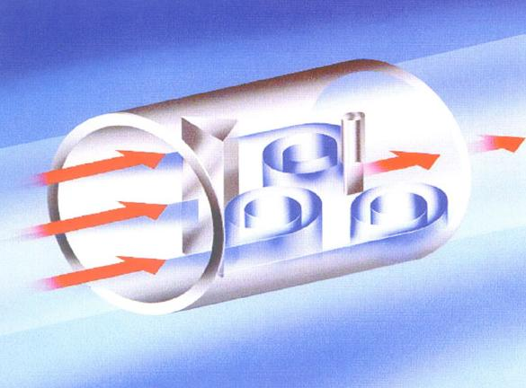
The frequency at which these vortices are shed is directly proportional to fluid velocity, expressed by the Strouhal relationship:
f = St × V / d
Where f is the vortex shedding frequency, St is the dimensionless Strouhal number (typically 0.17–0.21 for most bluff body designs), V is the fluid velocity, and d is the width of the bluff body. Because the Strouhal number remains nearly constant across a wide Reynolds number range, the vortex frequency serves as a reliable, linear indicator of flow velocity.
Detection Methods
The vortices create oscillating pressure fluctuations that are detected by one of several sensing technologies embedded in or near the bluff body:
- Piezoelectric sensors: The most common type. A piezoelectric crystal generates a small voltage signal in response to the oscillating force from each vortex. These sensors have no moving parts and are highly reliable in steam and gas service.
- Capacitance sensors: Detect the pressure differential created by vortices using a flexible diaphragm. Less susceptible to vibration interference than some piezoelectric designs.
- Ultrasonic sensors: Some advanced designs use ultrasonic beams directed across the pipe bore to detect vortex-induced velocity fluctuations, enabling non-intrusive measurement.
Regardless of detection method, the output of a basic vortex flowmeter is a frequency pulse signal proportional to volumetric flow rate. Converting this to mass flow or standardized volumetric flow requires knowledge of fluid density — which is where compensation variants become essential.
Why Compensation Is Necessary for Accurate Flow Measurement
A vortex flowmeter's pulse output reflects actual volumetric flow at operating conditions — the real volume passing through the meter at that moment. For many liquid applications where density is relatively stable, this is sufficient. But for gases, steam, and supercritical fluids, the relationship between volumetric flow and mass flow is highly sensitive to both pressure and temperature.
Consider saturated steam at two different pressures:
- At 5 bar (absolute), saturated steam has a density of approximately 2.67 kg/m³
- At 10 bar (absolute), saturated steam density rises to approximately 5.16 kg/m³
The same volumetric flow reading at these two conditions represents nearly twice the mass flow at 10 bar compared to 5 bar. Without accounting for this density difference, a steam energy billing or process control system based solely on volumetric output would carry errors exceeding 30–50% under variable pressure conditions. Compensation directly addresses this by feeding real-time pressure and/or temperature data into the flow computer to calculate corrected values continuously.
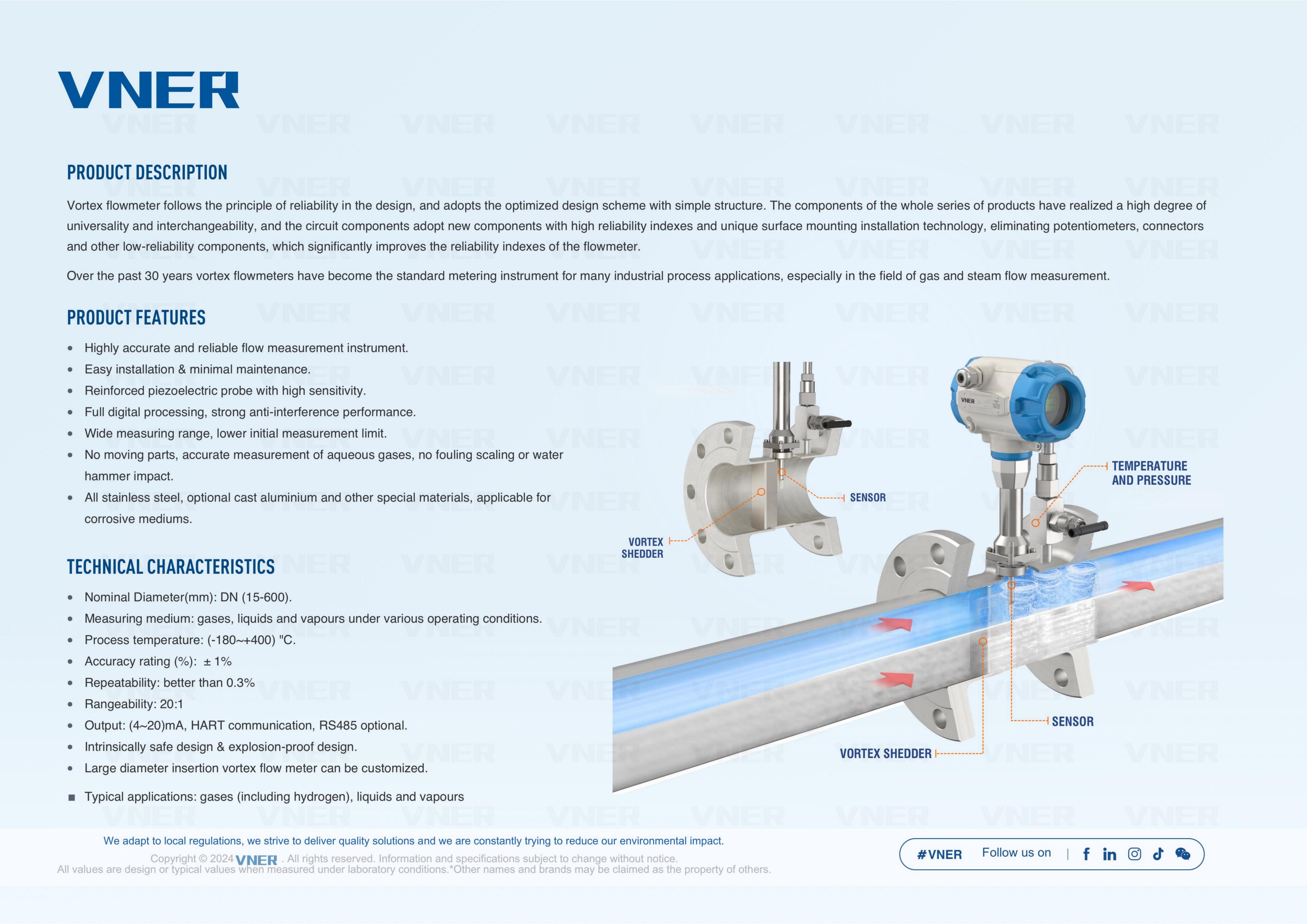
Pressure Compensation Vortex Flowmeter
A pressure compensation vortex flowmeter integrates a pressure transmitter — typically a piezoresistive or capacitance-type pressure sensor — into the meter body alongside the vortex detection element. The internal flow computer uses the live pressure reading alongside the measured vortex frequency to calculate fluid density from pre-loaded property tables, then derives mass flow or corrected volumetric flow in real time.
When Pressure Compensation Alone Is Sufficient
Pressure compensation is appropriate — and sufficient — when the fluid temperature is either constant or can be assumed constant within an acceptable tolerance. The most common scenario is saturated steam service: because saturated steam exists at a fixed temperature for any given pressure, measuring pressure alone fully defines the thermodynamic state of the fluid. No separate temperature measurement is required to determine density.
Additional suitable applications include:
- Compressed air systems where supply temperature is relatively stable but line pressure varies with compressor cycling
- Nitrogen or inert gas distribution at near-ambient temperature with variable header pressure
- Natural gas measurement where temperature variation is modest (within ±10°C of a reference value)
Typical Specifications
Most pressure compensation vortex flowmeters on the market feature integrated pressure sensors rated to 0–4 MPa or 0–10 MPa, with pressure measurement accuracy typically ±0.5% FS. The combined flow measurement uncertainty after compensation is generally in the range of ±1.0–1.5% of reading for steam and gas, compared to ±0.5–1.0% for the vortex element alone measuring volumetric flow in liquids.
Temperature Compensation Vortex Flowmeter
A temperature compensation vortex flowmeter integrates a resistance temperature detector (RTD) — most commonly a Pt100 or Pt1000 class A sensor — into the meter or its immediate upstream/downstream companion fitting. The temperature signal feeds the same internal flow computer, which uses fluid property data to derive density and calculate mass or corrected flow.
When Temperature Compensation Alone Is Used
Temperature-only compensation is less common than pressure-only or combined compensation, but has legitimate applications:
- Liquid flow at constant pressure but variable temperature: Hot water circuits, thermal oil systems, and cooling water loops where pipe pressure is regulated but temperature varies with process load
- Gas flow at known stable supply pressure: When a pressure regulator holds upstream pressure tightly but ambient or process temperature varies seasonally or diurnally
- Custody transfer of gases at regulated pressure: Where the pressure is fixed by contract or regulation and only temperature needs active monitoring
RTD Placement and Response Time
The RTD is typically installed in a thermowell positioned 3–5 pipe diameters downstream of the vortex meter body to avoid disturbing the flow profile at the measurement point. Thermowell design matters: a heavy-walled thermowell increases thermal lag, which can introduce transient errors during rapid temperature changes. For processes with fast temperature swings, a reduced-tip or fast-response thermowell with a response time under 5 seconds is recommended.
Combined Pressure and Temperature Compensation Vortex Flowmeter
The most capable and widely specified variant integrates both pressure and temperature sensors into a single meter assembly. With access to both variables simultaneously, the internal flow computer can apply the full equation of state for the fluid — yielding true mass flow calculation without any assumptions about operating conditions.
This configuration is mandatory for:
- Superheated steam: Unlike saturated steam, superheated steam exists at temperatures above the saturation curve for any given pressure. Both pressure and temperature are independently variable and must both be measured to determine density from steam tables.
- Natural gas custody transfer: AGA (American Gas Association) and ISO standards for natural gas measurement require correction to base conditions using both pressure and temperature
- Variable process gases: Mixed gas streams, biogas, or process off-gas where composition and operating conditions both fluctuate
- Steam energy metering for billing or allocation: Where BTU or kJ output must be calculated accurately across changing load conditions
Manufacturers such as Yokogawa (digitalYEWFLO series), Endress+Hauser (Prowirl F 200), and Emerson (Rosemount 8800D MultiVariable) offer fully integrated multivariable vortex flowmeters that measure vortex frequency, pressure, and temperature in a single process connection, outputting mass flow directly via HART, FOUNDATION Fieldbus, or Modbus protocols.
Comparison: Standard vs Compensated Vortex Flowmeters
| Variant | Integrated Sensors | Output Type | Typical Accuracy | Primary Application |
|---|---|---|---|---|
| Standard Vortex | Vortex sensor only | Actual volumetric flow | ±0.5–1.0% of reading | Liquids at stable conditions |
| Pressure Compensation | Vortex + pressure | Mass flow / corrected volume | ±1.0–1.5% of reading | Saturated steam, compressed gas |
| Temperature Compensation | Vortex + RTD | Mass flow / corrected volume | ±1.0–1.5% of reading | Hot liquids, regulated-pressure gas |
| P + T Compensation | Vortex + pressure + RTD | True mass flow | ±1.0–2.0% of reading | Superheated steam, natural gas, process gas |
Installation Requirements That Affect Accuracy
Regardless of compensation configuration, vortex flowmeters are sensitive to flow profile distortions caused by upstream piping geometry. Meeting straight-run requirements is non-negotiable for achieving rated accuracy.
Upstream and Downstream Straight Pipe Requirements
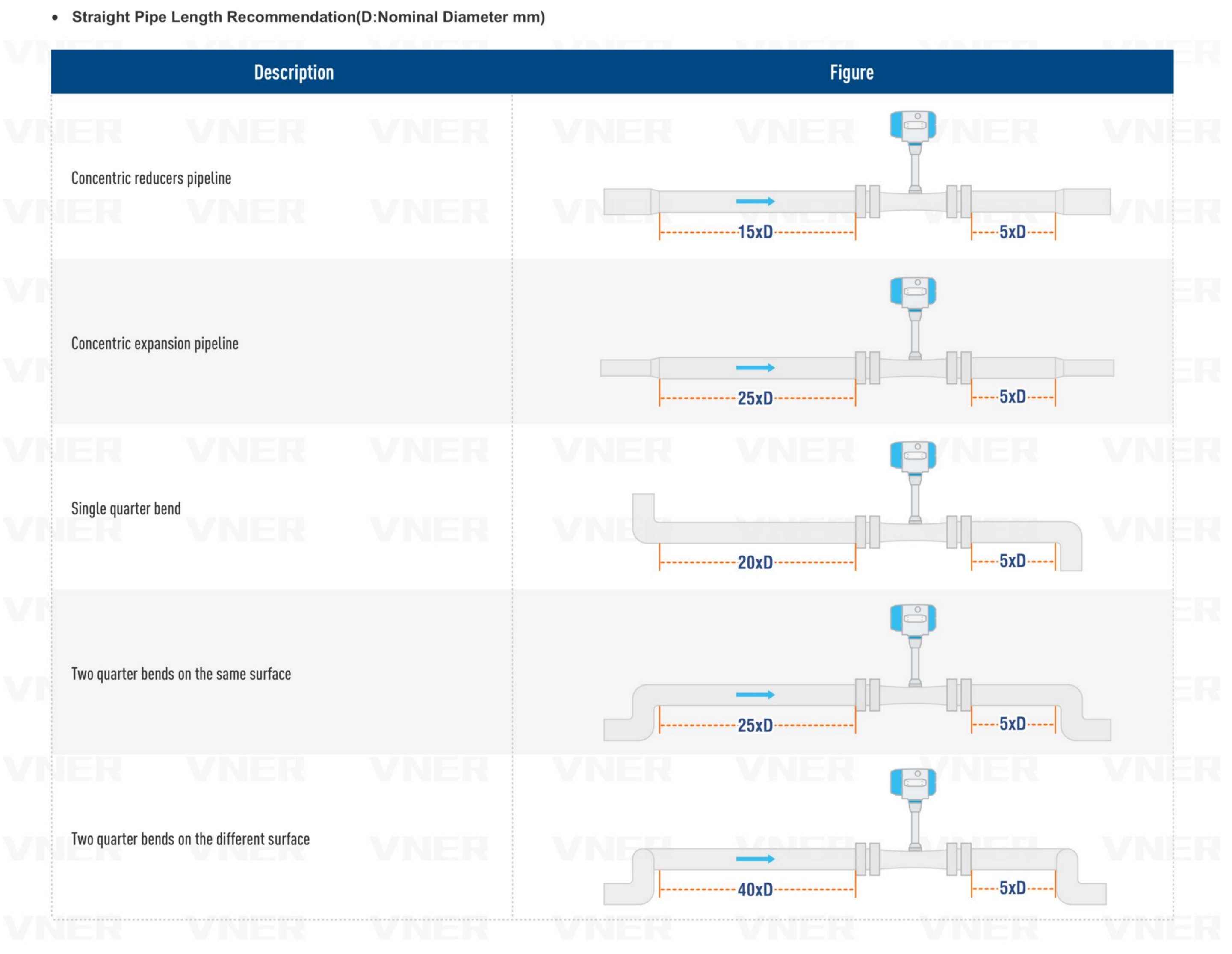
The following straight-run requirements apply to most vortex flowmeters under standard installation conditions. Actual requirements vary by manufacturer and meter design:
| Upstream Disturbance | Minimum Upstream Straight Run | Minimum Downstream Straight Run |
|---|---|---|
| Single 90° elbow | 15–20 × D | 5 × D |
| Two 90° elbows (same plane) | 20–25 × D | 5 × D |
| Two 90° elbows (different planes) | 40 × D | 5 × D |
| Partially open valve | 40–50 × D | 5 × D |
| Reducer (2:1) | 10 × D | 5 × D |
Vibration and Pulsation Sensitivity
Vortex flowmeters are inherently susceptible to mechanical vibration because their sensors detect oscillating forces. Pipeline vibration at frequencies close to the vortex shedding frequency can cause false pulses, signal dropout, or erratic readings. Most modern digital signal processors include adaptive filtering to discriminate between vortex signals and vibration noise, but severe vibration environments — near compressors, pumps, or steam turbines — should be evaluated carefully. Mounting the meter on a vibration-isolated spool piece or relocating it further from the vibration source are practical remediation strategies.
Flow Range and Minimum Flow Considerations
Every vortex flowmeter has a minimum measurable flow velocity — typically 0.5–1.0 m/s for liquids and 3–5 m/s for gases and steam — below which vortex shedding becomes irregular and the signal unreliable. This lower threshold is often called the cutoff velocity or minimum detectable flow. Below this point, the meter outputs zero regardless of actual flow, which must be accounted for in applications with wide turndown requirements.
The practical turndown ratio for most vortex meters is 10:1 to 20:1, compared to 100:1 or more for Coriolis or magnetic flowmeters. For steam systems that regularly operate at low load — for example, during plant startup or overnight — this limitation can cause significant metering gaps unless the meter is sized conservatively for the maximum expected flow rather than the average.
A useful sizing rule: select a meter size where the normal operating flow velocity falls between 3 and 15 m/s for gas/steam and between 1 and 7 m/s for liquids. This ensures the operating point stays well within the linear range while leaving headroom for flow surges.
Selecting the Right Vortex Flowmeter Configuration
Use the following decision criteria to identify the appropriate vortex flowmeter variant for your application:
- Identify your fluid phase and variability: Liquid at stable conditions → standard vortex. Saturated steam or gas with variable pressure → pressure compensation. Superheated steam, natural gas, or any gas with both pressure and temperature variation → combined P+T compensation.
- Determine whether mass flow or volumetric flow is required: Energy billing, custody transfer, and combustion control typically require mass flow. Tank filling or process batching may only need volumetric flow, in which case a standard or single-compensation meter may suffice.
- Check Reynolds number at minimum flow: Vortex meters require a minimum Reynolds number of approximately Re = 20,000 for reliable shedding. For viscous liquids or very low-flow conditions, this threshold may not be achievable and an alternative technology should be considered.
- Assess the installation environment: High vibration, pulsating flow, or insufficient straight run may require a different meter technology or significant piping modifications before vortex metering is viable.
- Evaluate communication and integration requirements: Compensated vortex meters output multiple process variables. Confirm that the control system or data acquisition infrastructure supports the meter's output protocol — HART, Profibus, or FOUNDATION Fieldbus — before specifying a multivariable unit.
For the majority of steam energy metering applications — which represent the largest single use case for compensated vortex flowmeters — a combined pressure and temperature compensation unit is the correct specification. The marginal cost over a pressure-only model is modest, while the accuracy improvement for superheated steam service is substantial and often required by site energy management standards such as ISO 50001.
We offer all our products and services at international standards.
Products
Contact Information
-

+86-18652789521
+86-18052582295
+86-0514-83633600 / 83633900 -

+86-0514-83633600 / 83633900
-

-

No. 11 Xingye Road, Chenji Town Industrial Park, Yizheng, Yangzhou, China
