
 0
0
 EN
EN  English
 عربى
عربى Español
 русский
If you need any help, please feel free to contact us
Home / News / Industry News / Mass Flow Rate Explained: Definition, Formula, Measurement and Industrial Applications
Mass Flow Rate Explained: Definition, Formula, Measurement and Industrial Applications
A process engineer at a polymer plant notices an 8.4 percent discrepancy in the daily material balance. The feed line to the reactor reports 1,800 m³/h of propylene gas at 1.1 bar and 30°C, but the upstream mass balance says the actual flow should be closer to 2,050 kg/h. When the engineer converts the volumetric reading using the real density of propylene at those conditions, the mass flow rate turns out to be only about 1,870 kg/h. In a site where every kilogram of monomer changes production economics, that 5.5 percent gap means thousands of tonnes of raw material are lost or unaccounted for each year.
The problem is not the flow meter itself. It is the decision to treat a volume-based measurement as a mass-based value. Mass flow rate is the variable that belongs in reaction stoichiometry, energy balances, custody transfer agreements, and environmental reporting. It does not change when pressure or temperature changes, because the same physical material is still moving through the pipe. A volumetric flow reading, by contrast, is a snapshot of the space the material occupies, and that space changes with every shift in process conditions. When you specify an instrument for a process line, the first question is not which brand or model to buy. The first question is whether the instrument will provide a true mass flow rate or a volumetric value that still has to be converted.
What Mass Flow Rate Actually Means
Mass flow rate is the mass of a fluid that passes through a given plane per unit of time. In the SI system, the unit is the kilogram per second (kg/s). In practical process engineering, it is also expressed as kilograms per hour (kg/h), tonnes per hour (t/h), pounds per hour (lb/h), or, for gases, as normal cubic meters per hour (Nm³/h) and standard cubic feet per minute (SCFM). Those gas units are already mass-based values referenced to a fixed density, so they are mass flow rates, not true volumetric flow rates.
The basic equation
The formal definition is the derivative of mass with respect to time, written as dm/dt. For steady flow through a pipe, the practical form is:
Mass flow rate = fluid density × volumetric flow rate = fluid density × cross-sectional area × average velocity.
Density is expressed in kg/m³, volumetric flow rate in m³/s, area in m², and velocity in m/s. This equation works for liquids, gases, and heterogeneous mixtures as long as the density and velocity values represent the actual flowing fluid. For a gas, density depends on pressure, temperature, and composition; for a liquid, it depends on temperature and composition; for a slurry, it depends on solids concentration and particle distribution.
Why the continuity equation points to mass
The principle of conservation of mass says that, for steady conditions, the mass flow rate entering a pipe section equals the mass flow rate leaving it. A fluid can change its volume when pressure or temperature changes, but it cannot change its mass without leakage, accumulation, or a chemical reaction. This is why mass flow rate is the consistent reference frame for process engineers. If a volumetric meter reads 100 m³/h at the inlet of a compressor and the gas is then compressed to a higher pressure, the outlet volumetric flow may be only 25 m³/h, but the mass flow rate is the same. An engineer who sees only the inlet reading and tries to set an outlet mass balance from volume will be misled.
Units and conversion factors
The common conversions are simple but easy to get wrong. One kg/s equals 3,600 kg/h, 3.6 t/h, and about 7,936 lb/h. A gas flow measured in Nm³/h is converted to mass flow by multiplying by the density at the reference condition, which is often 1.293 kg/m³ for air at 0°C and 1.01325 bar absolute. If the reference condition in a project specification is 20°C and 1.01325 bar, the reference density is different, and using the wrong one introduces a systematic error that can exceed 4 percent. Verify the reference condition in every datasheet before comparing gas mass flow values.
Mass Flow Rate vs Volumetric Flow Rate
Volumetric flow rate is the volume of fluid that passes through a specific plane per unit of time. It is expressed in m³/h, L/min, or ft³/s. It is the flow rate that is easiest to visualize, but it is also the one that depends most strongly on process pressure and temperature. A piston pump moves a nearly constant volume of liquid per stroke, so a volumetric reading is useful for tracking pump output. A gas burner, however, needs a specific mass flow of fuel to produce a specific heat release. A volumetric gas reading at 10 bar and 20°C will represent roughly ten times more mass than at 1 bar and 20°C, even though the volume flow number is identical.
The density problem
Density is the bridge between volume and mass. For an ideal gas, density is proportional to absolute pressure and inversely proportional to absolute temperature. A gas at 2 bar absolute and 300 K has about twice the density of the same gas at 1 bar absolute and 300 K. A temperature change from 20°C to 50°C reduces gas density by about 10 percent, which creates a 10 percent error in mass flow if the volumetric meter reading is used without correction. For liquids, density increases when temperature drops and may increase with dissolved solids or suspended particles. A 5 percent density error becomes a 5 percent mass flow error, which is often enough to fail a custody transfer tolerance.
Why process engineers prefer mass flow
Reactions are controlled by molar quantities, and molar quantities are proportional to mass, not volume. Heating value of a fuel gas is proportional to mass for a fixed composition. Steam load and turbine output are tied to mass flow. Wastewater treatment dosing is based on mass load. In each case, the process control target is a mass value, so the measurement should be a mass value or a volumetric value with reliable density correction. The table below highlights the practical differences.
| Feature | Mass Flow Rate | Volumetric Flow Rate |
|---|---|---|
| Definition | Mass of fluid passing a point per unit time | Volume of fluid passing a point per unit time |
| Typical units | kg/s, kg/h, t/h | m³/h, L/min, ft³/s |
| Sensitivity to pressure | None for the measured mass | Gases expand or compress with pressure |
| Sensitivity to temperature | None for the measured mass | Volume changes with thermal expansion |
| Best suited for | Material balance, custody transfer, combustion control | Pump sizing, line velocity checks, hydraulic calculations |
| Typical converted value | Nm³/h, SCFM for gases at reference conditions | Actual m³/h at flowing conditions |
Calculating Mass Flow Rate from Other Measurements
When a direct mass flow instrument is not available, mass flow rate must be calculated from a volumetric measurement and density, or from a differential pressure measurement. Each method has its own uncertainty budget and each requires careful attention to the operating point.
From volumetric flow and density
The simplest equation is mass flow rate = volumetric flow rate × density. For a liquid, density is often obtained from a reference table at the measured temperature. For a gas, density must be calculated from pressure, temperature, and composition, using the ideal gas law with a compressibility factor Z. The formula for a gas mass flow rate expressed in kg/h is:
Mass flow rate = volumetric flow rate (actual m³/h) × absolute pressure (Pa) / (Z × specific gas constant × absolute temperature in K).
If the volumetric flow meter measures in actual m³/h, the density calculation should use the actual pressure and temperature. If it measures in Nm³/h, the conversion to mass flow only requires the reference density and does not require live temperature and pressure correction.
From differential pressure
Differential pressure devices, such as orifice plates, venturi tubes, and averaging pitot tubes, infer flow from the pressure drop across a restriction. The general equation is:
Mass flow rate = discharge coefficient × expansion factor × area of the restriction × square root of (2 × density × differential pressure).
The discharge coefficient depends on Reynolds number and the geometry of the primary element. Standards such as ISO 5167 define the geometry, installation requirements, and uncertainty calculations. A common mistake is using the discharge coefficient for a sharp-edged orifice when the installation upstream does not allow the required straight pipe length. That can produce an error of 1 to 3 percent, even when the differential pressure transmitter is accurate.
From velocity and area
For velocity-based instruments such as insertion flow meters, the mass flow rate is the product of density, cross-sectional area, and average velocity. The average velocity is not the same as the centerline velocity. In a fully developed turbulent flow profile, the average velocity is roughly 0.81 to 0.83 times the centerline velocity, depending on the Reynolds number. Using the centerline value directly can overstate the flow by as much as 20 percent.
Worked example for a gas line
A 100 mm schedule 40 pipe carries natural gas at 4.5 bar gauge and 35°C. The differential pressure across a calibrated orifice plate is 2,400 Pa. The gas composition gives a density of 5.3 kg/m³ at the operating condition. With a discharge coefficient of 0.61, an internal orifice diameter of 60 mm, and an expansion factor close to unity, the mass flow rate is approximately 0.48 kg/s. If the same differential pressure is used with a density of 2.6 kg/m³ because the pressure was entered as 2.5 bar instead of 4.5 bar, the computed mass flow drops to 0.34 kg/s, a 29 percent error that would never be noticed on a field gauge but would turn up in the monthly reconciliation.
Uncertainty propagation
Every input variable in a mass flow calculation carries uncertainty. A volumetric flow meter at 1 percent uncertainty, combined with a density calculation at 0.5 percent uncertainty, yields a mass flow uncertainty of about 1.1 percent if the errors are independent and combined in quadrature. If the density uncertainty is 2 percent because composition is not precisely known, the mass flow uncertainty becomes 2.2 percent. This secondary uncertainty is one reason why direct mass flow measurement is preferred in applications where the density input is uncertain.
How Mass Flow Rate Is Measured in Industry
Industrial flow meters use different physical principles to measure mass flow. Some measure mass directly. Others measure velocity or volume and then rely on additional inputs to compute a mass value. The selection of the right family is the most important accuracy decision you will make.
Coriolis mass flow meters
Coriolis flow meters measure mass flow rate directly by tracking the phase shift caused by the Coriolis force in a vibrating tube. The fluid passes through one or two curved tubes that are excited at a known frequency. When mass flows through the tube, the Coriolis force causes a twist in the vibration, and the phase difference between two points on the tube is proportional to the mass flow rate. Because the measurement is directly tied to mass, there is no need for separate density compensation.
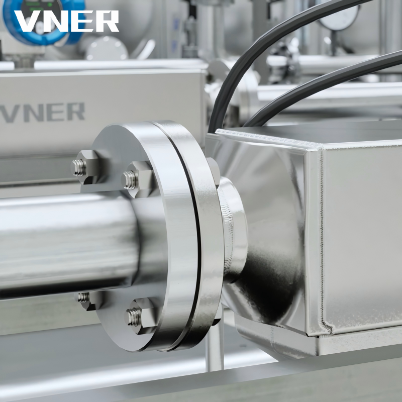 AC Series Coriolis Mass Flowmeter for Direct Mass Flow MeasurementThis Coriolis meter directly measures mass flow, density, and temperature, eliminating the need for separate density compensation. Its stable performance and high accuracy make it suitable for custody transfer and critical process control.View Product →
Coriolis meters are available in a wide range of line sizes and can handle liquids, gases, and slurries. A high-performance liquid measurement can achieve an accuracy of about ±0.1 percent of reading with repeatability of ±0.05 percent. For gas measurement, a typical accuracy range is ±0.25 to ±0.5 percent of reading, depending on operating pressure and meter size. The most valuable feature is stability over time. Because there is no calibration drift due to density or pressure assumptions, the meter can remain in service for years without the need for field correction, provided the tubes remain clean and the zero point is verified.
The mechanical measurement principle makes the meter sensitive to vibration, two-phase flow, and high viscosity. When you want to understand the physical effect in detail, it is worth knowing exactly how Coriolis mass flow meters work, especially the difference between phase shift, frequency, and damping, because that knowledge helps you define the right installation conditions.
Thermal mass flow meters
Thermal mass flow meters measure mass flow rate by sensing the heat transfer from a heated element to the flowing gas. For a clean, dry gas, the heat transfer is directly related to the mass flow rate. The measurement principle is particularly useful for low-pressure or low-velocity gas flows, and it does not require temperature or pressure compensation for mass flow because the thermal response is a function of mass and specific heat. Typical accuracy is ±1 percent of full scale, and repeatability can be very good. The main limitation is that the meter must be calibrated for the specific gas composition, because specific heat capacity changes with composition. Wet, dirty, or non-homogeneous gas streams can also affect the heat transfer behavior.
Vortex and swirl flow meters with temperature and pressure compensation
Vortex flow meters measure the frequency of vortices shed behind a bluff body. The frequency is proportional to the velocity of the fluid, not to its mass. To obtain a mass flow reading, the meter must combine the measured velocity with a density value. Swirl flow meters use a similar principle, but they generate a precession around the axis of the meter. Both families can be equipped with integrated pressure and temperature sensors so that the flow computer can density-compensate the reading for the actual operating conditions.
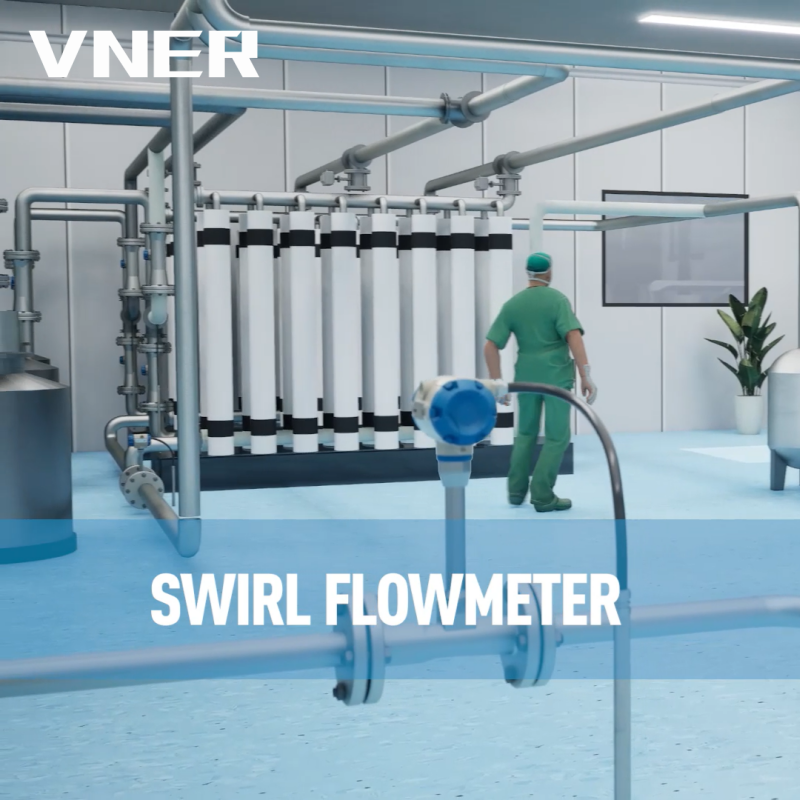 SA80T-TP Series Swirl Flowmeter with Integrated Temperature and Pressure CompensationThe SA80T-TP integrates temperature and pressure sensors to compute real-time density, providing mass flow and standard volume flow. It is ideal for steam and compressed air networks where compensated readings are essential.View Product →
This approach is widespread in gas and steam service. A vortex or swirl meter with pressure and temperature compensation can deliver an accuracy of about ±1.0 percent to ±1.5 percent of reading for mass flow, which is enough for many process control applications but not for custody transfer. The key is to make sure the compensation inputs are truly representative of the flowing stream. If the pressure tapping point is upstream of the meter and the pipe has a pressure drop, the density calculation will be slightly wrong.
Turbine flow meters
Turbine flow meters measure the rotational speed of a rotor, which is proportional to the fluid velocity. The meter itself is a volumetric device. To convert the reading to mass flow rate, the operator must provide the density at the operating condition. Turbine meters provide excellent repeatability and are common in metering applications for clean, low-viscosity liquids. The VNER LWQ gas turbine flowmeter and LWGY liquid turbine flowmeter are built around this principle. For gas service, different rotor designs are used, and the density at the operating point must be calculated from pressure and temperature.
Electromagnetic flow meters
Electromagnetic flow meters use Faraday's law to measure the velocity of a conductive liquid. The measurement is volumetric, not mass-based. To obtain mass flow, the density of the liquid must be entered into the converter or supplied by a separate density measurement. For liquids with a stable density, such as water or a dilute acid at a fixed composition, the volumetric reading can be converted to mass with acceptable accuracy. For varying density streams, such as slurries or mixtures with changing solids concentration, an electromagnetic flow meter alone is not sufficient for a reliable mass value, and a density source is needed.
Choosing the Right Mass Flow Measurement Approach
The right flow meter depends on the fluid, the process conditions, the required accuracy, the installation constraints, and the maintenance budget. There is no single universally correct answer. The table below compares the principal technologies and gives a first-pass screening view.
| Technology | Mass / Volumetric | Typical Accuracy | Recommended Fluids |
|---|---|---|---|
| Coriolis | Direct mass | ±0.1% to ±0.5% of reading | Liquids, gases, slurries |
| Thermal | Direct mass (gas) | ±1% of full scale | Clean dry gases |
| Vortex / swirl | Volumetric + compensation | ±1% of reading | Liquids, gases, steam |
| Turbine | Volumetric + density input | ±0.5% of reading | Clean low-viscosity liquids, gases |
| Magnetic | Volumetric + density input | ±0.2% to ±0.5% of reading | Conductive liquids |
Fluid phase and properties
A clean, low-viscosity liquid at a stable temperature can be measured well with a magnetic meter and a density input. A liquid with changing density, such as a slurry or a prepared polymer solution, is better served by a Coriolis meter. A clean gas with stable composition is a good fit for a thermal or compensated vortex meter. A gas with entrained droplets or particles is problematic for thermal meters and may be better served by a Coriolis meter, provided the meter is selected with sufficient pressure drop and tube geometry to handle the mixture.
Accuracy requirements and uncertainty budget
Custody transfer and fiscal metering require accuracy levels around ±0.1 to ±0.25 percent, so Coriolis or a well-calibrated turbine meter with density compensation is the usual choice. Process control loops typically need ±1 percent or better, which allows the use of compensated vortex or swirl meters. Material balance and energy accounting often require a long-term repeatability better than ±0.5 percent. It is important to distinguish between accuracy and repeatability. Two meters with the same accuracy can behave very differently over an annual period, so repeatability is often the decisive criterion for long-term material balance.
Process conditions and installation
Pressure and temperature limits are important. A Coriolis meter is a moderate pressure-drop device, so a low-pressure gas line may not have enough pressure budget for it. A thermal meter has a very low pressure drop and is preferred for low-pressure gas. A vortex or swirl meter needs a certain minimum velocity to create a signal, so it cannot be used at very low flow rates. Straight pipe run requirements also vary. Coriolis meters are relatively insensitive to upstream disturbances, whereas vortex and swirl meters often require 10 to 25 pipe diameters of upstream straight pipe, and magnetic meters need even more.
Maintenance and verification
Coriolis meters have no moving parts in the flow stream, but the sensor tubes can be coated by sticky process fluids. Verification usually consists of checking the zero point and comparing the measured density against a lab sample. Vortex and swirl meters have the advantage of no moving parts, but their sensors can be damaged by excessive vibration or by impurities if they are not installed with a strainer. Thermal meters need calibration at the specific gas composition. Turbine meters have moving bearings, which are the most likely component to fail, especially in dirty gas or abrasive liquids.
Common Mistakes and Procurement Risks
Treating volumetric readings as mass flow
This is the single most expensive error in the industry. A meter that shows 500 m³/h of gas at 1 bar and 25°C is carrying a much smaller mass flow than the same meter showing 500 m³/h at 8 bar and 25°C. If the engineering team writes the datasheet as 500 Nm³/h but the meter is calibrated in actual m³/h, the resulting mass flow will be off by the ratio of actual density to reference density, which can be a factor of 7 or more for high-pressure gas.
Ignoring gas density corrections
Even when a volumetric meter is used intentionally, a single density value is often entered into the flow computer and never updated. Over a year, a gas treatment plant may operate at different pressure and temperature setpoints, and the density at the flow meter may change by 15 to 20 percent. A static density value causes a systematic mass flow error that eventually becomes visible in the plant's overall material balance.
Improper straight pipe runs
Vortex, swirl, and differential pressure flow meters require specific upstream straight pipe lengths to develop a stable flow profile. A single 90-degree elbow just upstream of the meter can create a swirl that alters the calibration and produces errors of several percent. The usual remedy is to install the meter with more than 20 diameters of upstream pipe or to use a flow conditioner. Failing to do this is one of the most common causes of poor performance on a new installation.
Wrong calibration conditions
A flow meter calibrated with water but used on a gas stream will have a very different Reynolds number range. This can change the discharge coefficient or the K-factor. For volumetric meters, the calibration is often done at factory conditions with a specific viscosity and density. If the process fluid has a very different viscosity, the calibration curve should be adjusted or the meter should be calibrated with a fluid that matches the process properties.
Missing pressure and temperature compensation
When specifying a vortex or swirl meter for gas, the compensation is mandatory if the meter is expected to output mass flow. Some buyers order a standard vortex meter and expect the flow computer to use a fixed density. If the pressure varies and the compensation is not installed, the output is wrong. The supplier should describe exactly how the compensation is configured and where the pressure and temperature sensors are located.
Procurement risk: buying the wrong family
A common project procurement sequence is to purchase volumetric meters early and then discover in commissioning that the process needs mass flow. The result is a partial redesign, an approval document change, and a delay. Writing the measurement purpose into the datasheet from the beginning is the cheaper approach. State whether the output must be mass flow, which units are required, and which accuracy at which operating point is mandatory. Any supplier can then quote the correct technology from the start.
Mass Flow Rate Applications Across Industries
Mass flow rate shows up in every process industry, but the pressure to measure it accurately is highest where material balance, energy cost, and contract revenue are at stake.
Oil and gas and CNG
In oil and gas production, mass flow rate is used to allocate wells, monitor separator performance, and measure natural gas at custody transfer points. Compressed natural gas (CNG) is one of the most demanding applications because the gas is stored at high pressure and delivered with a fast-filling sequence that changes pressure and temperature rapidly. A volumetric meter at a CNG dispenser needs a complete pressure and temperature correction, or the displayed mass delivered will drift. A specialized Coriolis mass flow meter is designed for this duty because it measures mass directly and can respond quickly to changing flow conditions.
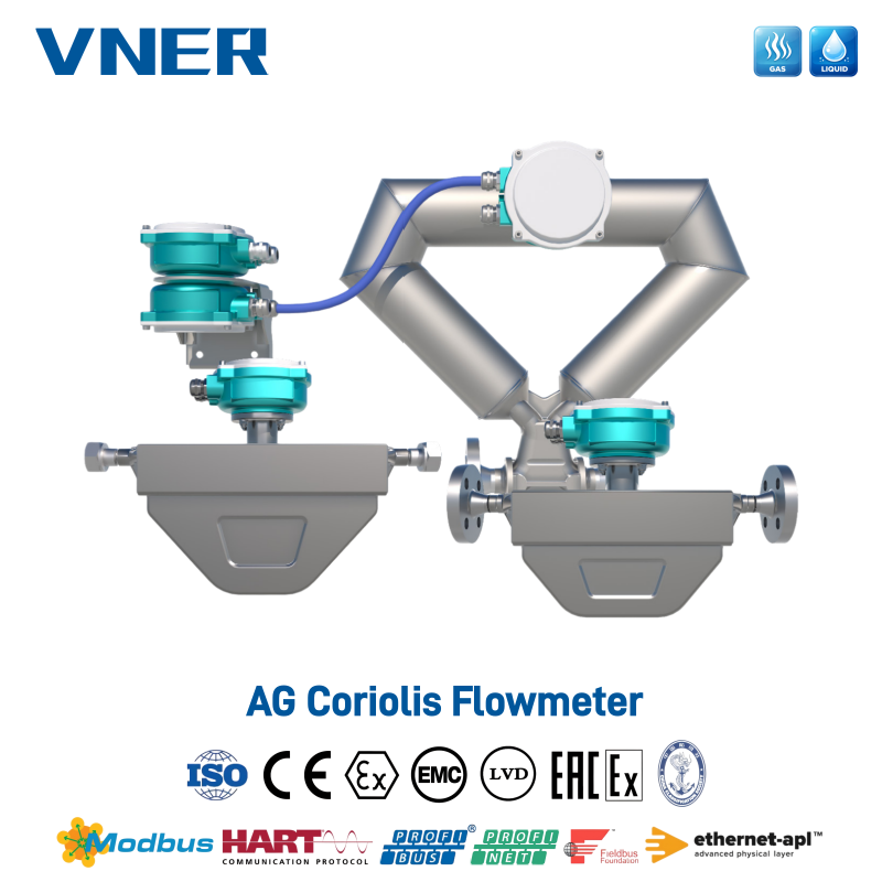 AG Series Coriolis Mass Flowmeter for CNG and LNG DispensingDesigned for CNG and LNG fueling, this Coriolis meter delivers direct mass flow measurement with certified batch accuracy of ±0.50%. It handles high pressure and cryogenic temperatures, ensuring reliable custody transfer.View Product →
VNER supplies the AG-CNG specialized Coriolis mass flow meter specifically for CNG dispensing and compression loops. This meter is part of the company's broader portfolio for the oil and gas sector, where accurate mass measurement supports billing, theft prevention, and compressor protection.
Petrochemical and chemical
Chemical plants rely on mass flow for reactor feed control, catalyst injection, and additive dosing. A slight error in the mass flow of a reactant changes the stoichiometric ratio and can lead to side reactions, off-spec products, or wasted catalyst. Coriolis meters are often used for this duty because they handle a wide range of densities and can be installed directly inline. Swirl and vortex meters with compensation are a common lower-cost alternative when the accuracy requirement is not as strict.
Polysilicon
In polysilicon production, gases such as trichlorosilane and hydrogen must be delivered with very precise amounts. The reactors operate at high pressure and temperature, and any misstatement of mass flow can affect the deposition rate and the crystal quality. Coriolis mass flow meters are used in this industry because they measure the actual mass of these gases and vapors without needing a separate composition analysis. The reliability of the meter over long operating cycles is as important as the accuracy, because a reactor outage is extremely expensive.
Power
Power plants use mass flow rate to monitor boiler feedwater, fuel gas, and steam output. In steam measurement, a vortex or swirl meter with temperature and pressure compensation is common because it can survive high temperatures and delivers a usable mass flow value. In boilers, the mass flow of fuel is directly related to heat input, so an inaccurate mass flow reading causes inefficient combustion and higher CO₂ emissions. The economic impact is visible in the fuel bill.
Water and wastewater
In water and wastewater treatment, mass flow rate is used for chemical dosing and solids loading calculations. Magnetic flow meters are a mainstay for volumetric flow measurement in water, but when the plant must control the mass of chlorine or polymer added per unit flow, the density must be known. A magnetic meter combined with a density measurement provides the mass flow. In wastewater with varying solids content, a direct mass measurement such as a Coriolis meter can reduce the uncertainty significantly, assuming the pipe size and pressure drop are compatible.
EPC projects and OEM integration
EPC contractors purchase flow meters in large quantities for process lines, and OEMs integrate flow meters into skids and packaged equipment. Both groups need consistent, repeatable instruments delivered on time with clear documentation. The engineering-driven sizing approach used by suppliers such as VNER is critical in this segment: the supplier calculates the expected flow range, pressure drop, and accuracy based on the process data, rather than merely quoting a catalog model. EPC engineers also need to know which units the meter outputs, how it communicates with the control system, and how the vendor supports commissioning and calibration.
Nowhere is this more visible than when the same mass flow rate must be measured across multiple process industries. The process industries served by this equipment share one common requirement: the flow output must be traceable to mass, whether the fluid is a gas, liquid, or slurry.
Engineering-Specific Guidance for EPC and OEM Projects
Data sheets and sizing requests
When a flow meter is specified, the datasheet must contain the fluid name, composition, operating pressure and temperature, density, viscosity, allowed pressure drop, pipe size, flow range, required accuracy, and output signals. Vague statements such as "suitable for natural gas" are not enough. The engineer should give both minimum and maximum flow rates. For a mass flow meter, the maximum flow rate determines the required sensor size, while the minimum flow rate determines whether the meter can resolve the flow without signal erosion. A Coriolis meter may have an excellent turndown, but at very low flow the density and zero stability become the limiting factors.
Vendor selection criteria
The supplier should demonstrate experience with the same fluid family and the same plant service. Reference installations, calibration facilities, and long-term support matter more than a large catalog. Check whether the supplier performs in-house calibration and how traceable that calibration is. For Coriolis meters, a zero-point verification and a density check at the operating conditions are useful acceptance tests. For compensated vortex or swirl meters, the vendor should disclose the compensation equation and the uncertainty under real operating pressure swings.
Interface with control systems
Mass flow meters typically provide a 4-20 mA signal, HART, Modbus, or Fieldbus. The control engineer needs to know if the flow signal is mass flow or volumetric flow, because the scaling in the DCS depends on this. For a meter with pressure and temperature compensation, the flow computer inside the transmitter is the one doing the density correction, and the DCS receives the mass flow directly. If the meter provides only volume and the DCS does the conversion, the DCS must have live pressure and temperature inputs, and the calculation must be verified against the meter's own calculation at commissioning.
Validation and commissioning
At commissioning, confirm that the meter reads zero with no flow and that the trim value is within the manufacturer's tolerance. Run a wet test with water if possible, or compare the meter against an existing calibrated flow meter on the same line. For gases, use a calibrated low-flow or high-flow test rig if available. Check that the pressure and temperature sensors used for compensation are correctly located, have appropriate spans, and that the values shown by the flow computer match a hand calculation of density.
Lifecycle cost considerations
Purchase price is only one part of the lifecycle. A meter with poor repeatability may force the process operator to overfeed or underfeed chemicals, and the operational cost can exceed the meter price in one month. A meter with high pressure drop may require a larger pump, increasing energy consumption. A meter that can be verified quickly and has no moving parts in contact with the fluid will usually have a lower total cost over ten years than a cheaper meter that requires frequent maintenance.
Conclusion
Mass flow rate is the quantity that really matters in process control, energy accounting, and product quality. A volumetric reading is useful for hydraulic sizing and pump selection, but it cannot stand in for a mass value unless the density is known and stable. In plants where pressure, temperature, or composition varies, the only reliable path is to measure mass directly with a Coriolis meter, or to add pressure and temperature compensation to a velocity-based meter.
For plant engineers, the most important habit is to verify the measurement purpose before selecting the technology. For EPC and OEM teams, the key is to give the supplier enough process data to size the meter correctly and to confirm the output units. For operators, the lesson is that a mass flow reading is not a number on a screen; it is the foundation of material balance, and it deserves the same attention as a laboratory analysis. When a company focuses on the whole path from sensing element to flow computer to control system, mass flow rate becomes a reliable decision tool rather than a source of daily discrepancies.

We offer all our products and services at international standards.
Products
Contact Information
-

+86-18652789521
+86-18052582295
+86-0514-83633600 / 83633900 -

+86-0514-83633600 / 83633900
-

shawn@vnerflow.com
info@vnerflow.com -

No. 11 Xingye Road, Chenji Town Industrial Park, Yizheng, Yangzhou, China
