
 0
 EN
 English
 عربى
 Español
 русский
If you need any help, please feel free to contact us
Home / News / Industry News / Natural Gas Flow Measurement: Matching Meters to Real Operating Conditions
Natural Gas Flow Measurement: Matching Meters to Real Operating Conditions
On a cold-start morning, a boiler house can show two different gas totals before anyone agrees on which one is right. The utility meter reports energy delivered at standard conditions. The plant submeter reports actual cubic meters at line pressure. The numbers are not necessarily wrong; they are answering different questions. Natural gas flow measurement becomes expensive when the purchase specification starts with a meter type instead of the quantity that must be reported, the conditions under which it must be reported, and the consequences of a wrong reading.
The practical conclusion is simple: specify natural gas flow measurement as a system, not as a box on a pipe. Start with the required reporting basis, then define pressure, temperature, composition, turndown, installation, verification, and lifecycle support. Only then choose among differential pressure, turbine, thermal mass, vortex, swirl, Coriolis, ultrasonic, rotary displacement, or variable-area technologies. A meter that is excellent in one service can be a maintenance problem in another, even when the data sheet looks similar.
This article explains how to make that decision in a way that survives commissioning, audits, and the first winter of real operation. It does not assume that a higher accuracy claim is automatically better. It focuses on the measurement uncertainty that remains after installation, compensation, calibration, and wear are taken into account.
Start With the Quantity You Need to Report
Natural gas is compressible, so a volumetric reading has no single meaning until the reference conditions are fixed. A meter may measure actual volumetric flow at 16 bar and 35 degrees Celsius, while a billing system needs standard cubic meters at 0 degrees Celsius and 101.325 kPa, or energy in megajoules. Mass flow may be the better choice for chemical consumption, fuel blending, or compressed natural gas. Energy may be the contractual basis for custody transfer. These are not interchangeable reporting choices.
Before comparing technologies, write down four numbers: the minimum flow, the normal flow, the maximum flow, and the design or upset flow. Then state the required uncertainty at each point, not only at full scale. Many procurement disputes begin because a meter is accurate at maximum flow but unreadable during purges, start-up, or low-load operation. The range is often wider than the project team first expects.
| Reporting basis | Physical meaning | Common unit | Main procurement implication |
|---|---|---|---|
| Actual volumetric flow | Volume at line pressure and temperature | m3/h at operating conditions | Useful for process control and pipe velocity checks; not sufficient for billing without compensation. |
| Standard volumetric flow | Volume corrected to an agreed reference pressure and temperature | Nm3/h or Sm3/h | Requires pressure, temperature, and sometimes compressibility correction. |
| Mass flow | Mass of gas passing the meter per unit time | kg/h or t/h | Useful when composition changes, when density is measured directly, or when chemical mass matters. |
| Energy flow | Mass or volume multiplied by heating value | MJ/h or kWh | Requires a heating value source, such as online analysis or a contractual gas composition. |
The reporting basis should be written into the datasheet and the purchase order. Otherwise the meter supplier, the control system integrator, and the billing group may use different assumptions. A flow computer configured for a fixed composition can be perfectly correct at commissioning and quietly wrong six months later if the gas source changes.
Why Natural Gas Rewards Careful Assumptions
Natural gas is not a single fluid with a fixed density. Pipeline gas may contain methane as the dominant component, with ethane, propane, butane, nitrogen, carbon dioxide, and traces of heavier hydrocarbons. The exact mix affects compressibility, density, viscosity, speed of sound, and heating value. A change in carbon dioxide or nitrogen content can shift the correction factors even when pressure and temperature remain stable.
Low density makes gas more sensitive to velocity profile and momentum effects than many liquids. At low pressure, the volume is large and the pipe velocity may be high. At high pressure, the gas is denser but still compressible. Pressure drop that would be trivial in a water line can become a real energy cost in a large gas main. Small temperature errors can also matter because the standard-volume correction is tied to absolute temperature, not to a simple linear rule of thumb.
Impurities create another layer of risk. Condensate, compressor oil, dust, and pipe scale can coat a thermal sensor, jam a turbine rotor, or alter a Coriolis tube's vibration. Pulsation from reciprocating compressors can disturb vortex and differential pressure signals. A meter that is clean in the laboratory may need a different installation, filtration strategy, or verification interval in the field.
A Practical Selection Sequence
The most reliable selection sequence is to reduce the problem from the commercial requirement down to the physical installation. This order prevents a common failure mode in which a preferred meter is chosen first and the process data are adjusted afterward.
- Define the contractual or operational quantity: actual volume, standard volume, mass, or energy.
- List the full operating map: minimum, normal, maximum, and upset flow, including start-up and purge conditions.
- Confirm pressure and temperature ranges, including transient conditions and ambient effects on transmitters.
- Obtain a representative gas composition and decide whether fixed, periodic, or online analysis is required.
- Set the required uncertainty and repeatability, not just a generic accuracy percentage.
- Review piping layout, straight runs, valves, elbows, filters, pulsation sources, and available maintenance access.
- Compare pressure loss, turndown, moving parts, calibration interval, and spare-part strategy over the expected life.
- Define verification: factory calibration certificate, site zero check, proving, comparison, or periodic laboratory recalibration.
This sequence also exposes where a project needs engineering support rather than a catalog number. VNER describes its approach as engineering-driven sizing and selection for liquid, gas, and slurry duties, with in-house calibration and project delivery experience. That kind of support matters when the datasheet includes a wide turndown, a changing composition, or a piping layout that cannot be changed. More detail is available on the company's about page.
Meter Technologies and Where They Fit
No single natural gas flow measurement technology wins every service. The useful question is not “which meter is best?” but “which measurement principle best tolerates the conditions that cannot be engineered away?” The notes below compare the technologies most often considered for industrial gas service.
Differential Pressure and Orifice Meters
Differential pressure meters, especially orifice plates, remain common in high-pressure gas because they are simple, well understood, and supported by long-standing standards such as AGA 3 and ISO 5167. They have no moving parts in the pipe, tolerate high temperature and pressure, and can be inspected without removing the whole meter body. The trade-offs are permanent pressure loss, a square-root relationship between differential pressure and flow, and a practical turndown that is narrower than many velocity meters. Installation depends heavily on correct straight runs, orifice condition, and transmitter accuracy. For large lines and custody-transfer stations, the orifice plate is often part of a carefully engineered measurement package rather than a standalone item.
Gas Turbine Meters
Turbine meters are velocity devices. The gas turns a rotor, and the rotor speed is related to actual volumetric flow. They offer good repeatability and fast response in clean, dry gas, and they are widely used in commercial and industrial metering. Their weaknesses are mechanical: bearings wear, dirt changes the rotor response, and over-speed or pulsation can shorten life. Upstream flow conditioning is important because swirl can bias the reading. A turbine meter is often a strong choice when the gas is clean, the pressure is stable, and the range is not extremely wide.
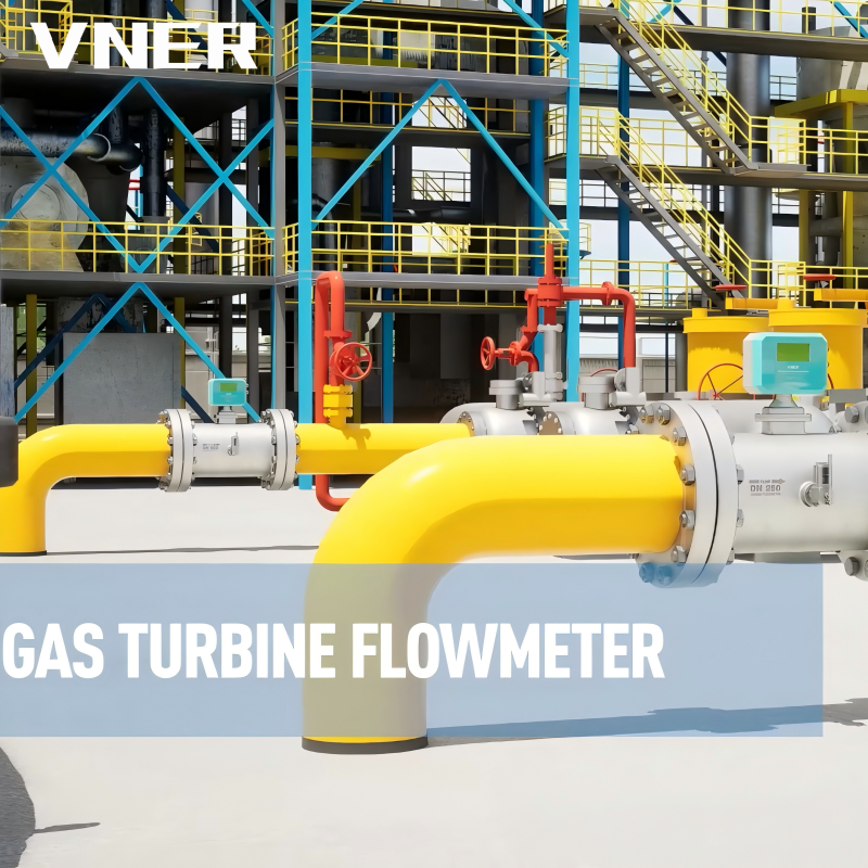 LWQ Series Gas Turbine FlowmeterHigh-accuracy turbine meter for clean, dry gases, with flow straightening, temperature/pressure compensation, low pressure loss, and good repeatability in commercial and industrial metering.View Product →
Rotary Positive Displacement Meters
Rotary displacement meters trap a known volume of gas and count the cycles. They are positive displacement devices, so they measure actual volume directly and can perform well at lower flow rates than some velocity meters. They are common in distribution and industrial sub-metering where the gas is clean and the line size is moderate. Mechanical clearances make them sensitive to dirt and condensate, and pressure loss rises as the meter wears or fouls. They are not the first choice for dirty gas, wet gas, or service with frequent overloads.
Thermal Mass Flow Meters
Thermal mass meters use a heated sensor and a reference sensor to infer mass flow from heat transfer. They are excellent at low gas flows, insert into large pipes with modest pressure loss, and are often used for combustion air, stack gas, aeration, and submetering. Their accuracy depends on the gas properties used during calibration. If the composition changes materially, a thermal meter calibrated for one natural gas mix may need a correction factor or a new calibration. They are not automatically “composition independent” simply because they report mass.
Vortex and Swirl Meters
Vortex meters create alternating vortices behind a bluff body, and the shedding frequency is proportional to velocity. They have no moving parts, tolerate reasonably high pressure and temperature, and work well in many gas, steam, and liquid services. Swirl meters use a different internal geometry to generate a precessing vortex, which can provide a compact alternative with good turndown and low maintenance. Both principles depend on Reynolds number and flow profile, so low-flow performance and installation conditions must be checked carefully. Pulsation and vibration are common enemies in compressor stations and reciprocating equipment areas.
Coriolis Mass Flow Meters
Coriolis meters measure mass flow directly by detecting the twist or phase shift of a vibrating tube. They also provide density, which can be valuable when gas composition changes. They achieve high accuracy and wide turndown in the right service, but they are generally limited to smaller line sizes and have a higher pressure drop than inline velocity meters. They are often used for compressed natural gas, fuel blending, and applications where mass or density is the primary requirement. They are rarely the economic choice for very large, low-pressure gas mains.
Ultrasonic Meters
Ultrasonic gas meters measure transit-time differences along one or more acoustic paths. They offer low pressure loss, wide turndown, and good performance in large pipelines when the flow profile is well conditioned. Multiphase or wet gas can degrade the signal, and the acoustic path must be designed for the expected pressure, temperature, and gas composition. They are often used in high-value custody-transfer and transmission applications, where the installed cost of a large meter station can justify the technology.
Variable-Area Meters and Other Choices
Variable-area meters, often called rotameters, provide simple local indication at modest cost. They are useful for purge flows, burner trains, and utility stations, but they are rarely suitable for custody transfer or high-accuracy reporting. Other choices include diaphragm meters for small consumer services and specialized flow computers or virtual measurement systems that calculate flow from pressure, temperature, and valve position. These methods can be useful for trend monitoring, but their uncertainty must be understood before they are used for billing or safety interlocks.
| Technology | Typical strength | Main limitation | Good fit when |
|---|---|---|---|
| Orifice / differential pressure | Simple, high-pressure capable, no moving parts in the pipe | Pressure loss, limited turndown, installation-sensitive | Large high-pressure gas lines and standard-based measurement stations |
| Gas turbine | Good repeatability and fast response in clean gas | Bearing wear, dirt sensitivity, flow-profile sensitivity | Clean, dry gas with stable pressure and moderate turndown |
| Thermal mass | Low-flow sensitivity and low pressure drop | Composition-dependent calibration | Submetering, combustion control, and low-pressure gas lines |
| Vortex / swirl | No moving parts and compact installation | Low-flow cutoff, vibration and pulsation sensitivity | Utility gas, steam-like service, and many industrial gas lines |
| Coriolis | Direct mass and density measurement | Higher cost and pressure drop; smaller line sizes | CNG, blending, and mass-based process control |
| Ultrasonic | Low pressure loss and wide turndown in large lines | Higher cost; signal quality depends on gas and profile | Large transmission and high-value custody-transfer lines |
Pressure, Temperature, and Reference Conditions
A volumetric meter measures the gas in front of it, not the gas the contract describes. Converting actual volume to standard volume requires absolute pressure, absolute temperature, and a compressibility factor. The common mistake is to use gauge pressure directly in the calculation. Another is to assume a fixed atmospheric pressure when the site altitude or weather changes the local absolute pressure. For high-pressure gas, even a small pressure-transmitter error can produce a visible billing difference.
The correction method should match the required uncertainty. A simple ideal-gas correction may be adequate for a utility submeter where the gas is near atmospheric pressure and the composition is stable. A custody-transfer station usually needs a recognized method such as AGA 8, a properly configured flow computer, and a documented procedure for composition updates. Temperature and pressure transmitters need their own calibration and installation review; a perfect meter with a drifting transmitter is still a drifting measurement.
Some applications benefit from an integrated approach. A temperature-pressure-compensated swirl meter, such as the SA80TTP, combines flow sensing with compensation in a compact package. That can simplify a skid or a retrofit where separate transmitters and a flow computer are awkward to install. It does not remove the need to agree on the reference conditions and the composition basis, but it can reduce field wiring and configuration risk.
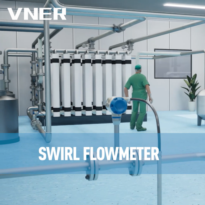 SA80T-TP Temperature and Pressure Compensated Swirl FlowmeterIntegrated temperature and pressure compensation for steam, compressed gas, and energy metering; calculates mass and standard volume flow while simplifying skid or retrofit installations.View Product →
Composition, Energy Content, and Custody Transfer
Custody transfer raises the stakes because the measurement becomes a commercial instrument. The contract may define the standard conditions, the heating value basis, the allowed uncertainty, and the verification method. Standards such as AGA 3 for orifice metering, AGA 7 for turbine metering, and AGA 9 for ultrasonic metering provide frameworks, but they do not design the station for you. The installer must still address straight runs, flow conditioning, transmitter calibration, gas composition, and data logging.
Energy measurement adds a heating value input. That input may come from a laboratory analysis, a contractual default, or an online gas chromatograph. A fixed heating value is acceptable only while the gas composition remains within an agreed band. When multiple gas sources enter a pipeline, the composition can change by time of day or season. The flow computer should have a clear procedure for updating composition and for recording when the update occurred.
Compressed natural gas is a special case. It is stored at high pressure, often dispensed in batches, and may be used as a vehicle fuel or an industrial feedstock. Mass-based measurement is attractive because it avoids some of the reference-condition arguments and provides a direct quantity for inventory. A Coriolis meter designed for CNG service can measure mass and density in a compact package, but the installer must still manage pressure drop, pulsation, and gas quality. VNER lists oil and gas, petrochemical, polysilicon, power, and water applications among its industry focus, which is a reminder that the same meter family may face very different site conditions across projects; see the industries page for the broader application map.
Installation Effects Are Part of the Measurement
A flow meter is a sensor in a piping system, not a standalone instrument. Elbows, tees, reducers, control valves, and compressors create swirl and asymmetry that can travel far downstream. The usual straight-run recommendations are a starting point, not a guarantee. Two 90-degree elbows in different planes can produce a worse profile than a single elbow, even when the measured centerline distance appears acceptable. Flow conditioners can help, but they add pressure loss and must be selected with the meter.
Pulsation is another common problem in natural gas systems. Reciprocating compressors, reciprocating pumps, and fast-acting valves can impose a periodic signal that the meter interprets as flow variation. Vortex meters may lock onto the wrong frequency, differential pressure transmitters may show noisy readings, and turbine rotors may suffer fatigue. A pulsation study, a dampener, or a different meter location may be more effective than adding signal filtering afterward.
| Field condition | Likely symptom | Practical mitigation |
|---|---|---|
| Close-coupled elbows or valves | Bias, repeatability loss, or noisy signal | Increase straight run, relocate the meter, or use a flow conditioner after review. |
| Liquid carryover | Erratic readings, coating, or mechanical damage | Add separation and drainage, heat trace where appropriate, and review materials. |
| Pulsating flow | Unstable output and apparent range exceedance | Relocate away from the source, add damping, or choose a more tolerant principle. |
| Vibration | False vortex shedding or sensor noise | Use anti-vibration mounts and verify the meter's vibration limits. |
| Transmitter elevation error | Zero offset in differential pressure measurement | Correct impulse-line layout and perform a documented zero check. |
Sizing, Turndown, and the Cost of Overranging
Size for the whole operating map, not for the nameplate maximum. A meter selected to read 100 percent of design flow at the top of its range may be outside its reliable range during normal operation. The opposite error also occurs: a meter selected for normal flow may be over-ranged during start-up, causing saturation or mechanical stress. The correct approach is to check minimum, normal, maximum, and upset points against the meter's published limits and against the Reynolds-number assumptions used in its calibration.
Turndown statements need careful reading. A ratio of 10:1 may refer to a laboratory calibration range, a specified accuracy band, or a mechanical limit. It may not apply at the same pressure and temperature as the project. For differential pressure meters, the square-root relationship means the low end is especially sensitive to transmitter zero and differential pressure resolution. For turbine meters, the low end may be limited by bearing friction. For thermal meters, the low end may be excellent, but the high end may be limited by sensor cooling or electronics.
A simple check is to plot the expected operating hours against flow. If the plant runs most of the year at 25 percent of design flow, the meter should be optimized for that region, not only for the design case. If the line must also pass a purge or a start-up surge, the meter should tolerate it without permanent damage. This is where a conversation with the supplier's application engineer is more valuable than a catalog comparison.
Calibration, Verification, and Lifecycle Risk
Every measurement drifts, fouls, or ages. The procurement question is not whether verification will be needed, but how it will be done and what happens to production during the check. A factory calibration certificate establishes a baseline, but it does not prove that the installed meter is correct. Installation effects, transmitter zero, impulse-line errors, and gas composition can all change the field result without changing the meter body.
For critical service, ask for a traceable calibration method, the uncertainty of the calibration rig, and the conditions under which the calibration was performed. Ask whether the meter can be verified in place, whether a bypass is available, and whether the meter can be removed without cutting the line. For meters with moving parts, ask for expected wear limits and recommended spare parts. For electronic meters, ask about diagnostics, signal quality, and the procedure for backing up configuration data.
VNER states that it uses in-house calibration and certified quality processes, and that its facilities include three plants with a technical team of about 150 people. Those facts are useful in a supplier review, but they should still be matched to the project's required documentation, traceability, and third-party inspection requirements. A capable factory is not a substitute for a clear calibration specification.
Datasheet and Procurement Details That Prevent Misapplication
Most misapplications can be traced to missing or ambiguous datasheet fields. The meter supplier may fill the gap with an assumption, and the buyer may not notice until commissioning. The following fields deserve a second review before the purchase order is released.
| Datasheet field | Why it matters | Example of a weak entry |
|---|---|---|
| Flow range | Sets turndown and low-end reliability | “Up to 5,000 m3/h” without minimum or normal flow |
| Reference conditions | Changes the reported volume and the correction method | “Standard conditions” without pressure and temperature values |
| Gas composition | Affects density, compressibility, heating value, and calibration | “Natural gas” with no range for nitrogen, carbon dioxide, or heavier hydrocarbons |
| Pressure and temperature | Determines materials, sensor type, and compensation range | Normal condition only, with no start-up or upset case |
| Accuracy and repeatability | Defines the acceptance test and the commercial risk | A single percentage with no statement of range or reference conditions |
| Installation layout | Controls flow profile and access for maintenance | No isometric drawing or straight-run dimensions supplied |
| Verification method | Determines lifecycle cost and production risk | “Calibration certificate required” with no traceability or interval defined |
Procurement should also confirm the interface details: power supply, output signals, communication protocol, enclosure rating, hazardous-area classification, material certificates, and documentation language. These items are not the core measurement principle, but they determine whether the meter can be integrated, inspected, and maintained without rework. A technically suitable meter that arrives with the wrong flange drilling or an incompatible output card is still a project delay.
Common Mistakes in Natural Gas Flow Measurement
Several mistakes appear repeatedly across projects of different sizes. They are not exotic; they are ordinary gaps between process data, instrument selection, and site execution.
- Choosing a meter by price before defining the reporting basis and the required uncertainty.
- Sizing only for maximum flow and ignoring the low-flow region where the plant actually operates.
- Treating “natural gas” as a fixed fluid with constant density and heating value.
- Using gauge pressure instead of absolute pressure in standard-volume correction.
- Assuming a thermal mass meter is immune to composition changes.
- Ignoring permanent pressure loss in a large gas main because the meter purchase price was lower.
- Approving a piping layout with insufficient straight run because the line was already fabricated.
- Forgetting that pulsation and vibration can affect vortex, turbine, and differential pressure meters.
- Buying a custody-transfer meter without agreeing on verification, proving, and data records.
- Leaving composition updates, alarm limits, and configuration backups undefined at handover.
Each mistake has a low-cost prevention: a completed datasheet, a piping review, a composition range, and a verification plan. The expensive version is discovering the gap after the line is pressurized and the commercial readings are already in use.
What a Good Measurement Decision Looks Like
A good natural gas flow measurement decision can be explained in one paragraph. The team knows which quantity must be reported, at which reference conditions, over which flow range, with which gas composition, and with what uncertainty. It has checked the piping layout, pressure loss, pulsation, and maintenance access. It has chosen a technology that tolerates the conditions rather than merely meeting a catalog accuracy figure. It has also defined how the meter will be calibrated, verified, and supported after commissioning.
That approach usually leads to a less dramatic purchase order and a more predictable operation. A differential pressure station may remain the right answer for a high-pressure main. A turbine meter may be the practical choice for clean gas and a stable range. A vortex or swirl meter may simplify a compact skid. A thermal mass meter may be the best fit for low-flow submetering. A Coriolis meter may be the cleanest way to measure CNG mass and density. The technology changes with the duty; the decision process should not.
Natural gas flow measurement is ultimately a chain of assumptions, and every link must be visible. Once the reporting basis, composition, installation, compensation, and verification are written down, the meter selection becomes more objective. The result is not just a reading on a screen, but a number that can be defended to operations, finance, and the customer at the other end of the pipeline.


Products
Contact Information
-

+86 18652789521
+86-0514-83633600 / 83633900 -

+86-0514-83633600 / 83633900
-

s@vner.com.cn
katherine@vner.com.cn -

No. 11 Xingye Road, Chenji Town Industrial Park, Yizheng, Yangzhou, China
