
 0
0
 EN
EN  English
 عربى
عربى Español
 русский
If you need any help, please feel free to contact us
Home / News / Industry News / Mass Flow Rate to Volumetric Flow Rate: Conversion Guide for Engineers
Mass Flow Rate to Volumetric Flow Rate: Conversion Guide for Engineers
A petrochemical facility in eastern China operated two flow meters in series on the same saturated steam header: a vortex meter downstream and a Coriolis mass flow meter upstream. For a full month the instruments tracked each other within two percent. Then the plant shifted steam load, the header pressure dropped by nearly four bar over a weekend, and the two readings diverged by eleven percent. The vortex meter, a volumetric device, was applying a fixed density that had been programmed at commissioning. The Coriolis meter was measuring mass directly. Neither meter was faulty. The error was conceptual: the plant had treated a volume reading as though it were a mass reading without re-examining the density.
Every engineer who has worked with flow instrumentation has met some version of this problem. The relationship between mass flow rate and volumetric flow rate looks deceptively simple: one equation, one density value. But density is rarely what the nameplate says. Getting the conversion wrong distorts material balances, undermines steam and energy accounting, wastes energy, and in extreme cases can push a process toward an unsafe operating state.
This article explains what each flow rate actually tells you, how to convert between them, what happens to density under real process conditions, which instrument technologies measure mass directly and which measure volume instead, and how to make the right selection for your service. The conclusion up front: mass flow is the physically conserved quantity that process economics and safety are built on; volumetric flow is a convenient proxy that is only reliable when density is known, stable, and correctly applied.
Mass Flow Rate and Volumetric Flow Rate: What Each Quantity Actually Tells You
Mass flow rate is the mass of fluid crossing a given cross-section per unit time. In industrial practice it is expressed in kilograms per hour, tonnes per hour, or pounds per minute. Mass is conserved in any ordinary process: it cannot be created or destroyed by changes in pressure, temperature, or phase. If a process appears to be losing or gaining mass, what you are actually seeing is a change in inventory, not a change in the mass number itself.
Volumetric flow rate is the volume of fluid crossing a cross-section per unit time, in cubic meters per hour or liters per minute. Volume is not conserved. The same kilogram of gas that occupies one cubic meter at atmospheric pressure occupies a fraction of that volume at higher pressure. A pump that delivers a constant volume per revolution will deliver very different mass flow rates depending on the density of the fluid entering it.
The practical consequence is simple and often overlooked: when the process question is phrased as "how much material is being produced, consumed, or transferred," the answer belongs on a mass basis. When the question is "how fast is this tank filling" or "what is the flow in this water pipe," a volumetric basis is natural and appropriate. Confusing the two is not a units problem; it is a meaning problem.
| Quantity | Common industrial units | Conserved when density changes? | Directly answers |
|---|---|---|---|
| Mass flow rate | kg/h, t/h, lb/min | Yes | How much material is truly moving? |
| Volumetric flow rate | m3/h, L/min, gpm | No | How much pipe volume passes per hour? |
The two quantities are connected by density. To obtain mass flow from volumetric flow, multiply by the density of the fluid at the meter's operating conditions. To obtain volumetric flow from mass flow, divide by that same density. The arithmetic is trivial. The engineering problem is determining which density value to use, and that is where most real-world errors begin.
The Conversion Formula: One Equation, One Catch
Where ṁ is the mass flow rate, Q is the volumetric flow rate, and ρ is the fluid density, the relationship is:
ṁ = Q × ρ, and therefore Q = ṁ / ρ
Work through a liquid example first. Water at 20 °C has a density of approximately 998 kg/m3. A line carrying 20 m3/h of water therefore carries 20 × 998 = 19,960 kg/h, or very nearly 20 tonnes per hour. Because water density changes slowly with temperature, this conversion remains valid for years when the temperature is stable.
Now take a gas example. Air at 25 °C and atmospheric pressure has a density of roughly 1.18 kg/m3. Twenty cubic meters per hour of that air equals only about 24 kg/h. Compress the same air to 6 bar absolute and the density rises to about 7.1 kg/m3; the same volumetric flow now represents about 142 kg/h. The volume number did not change, but the mass transported increased by a factor of six. Anyone who converted the first condition with the second density, or vice versa, would be off by hundreds of percent.
That is the catch in the title of this section: the conversion factor is itself a variable. For liquids it varies slowly. For gases it varies with every change in pressure and temperature. For steam it can vary dramatically across a modest pressure range.
There is a second catch related to reporting conventions. In natural gas and compressed air practice, flows are often stated in normal cubic meters per hour (Nm3/h) or standard cubic meters per hour (Sm3/h). These are not true volumetric flow rates at line conditions. They are mass flow rates expressed as the volume the gas would occupy at a fixed reference condition: 0 °C and 1.01325 bar for normal cubic meters, or 15 °C or 20 °C at the same pressure for standard cubic meters. A number reported as 10,000 Nm3/h is a mass flow of roughly 7,500 kg/h for a typical natural gas composition, regardless of the actual pressure in the pipe. Converting between actual volume, normal volume, and mass therefore requires that both the reference condition and the actual operating condition be stated correctly.
Density: The Bridge That Moves
Density is mass per unit volume. Its behavior under process conditions determines how much error you absorb when you use a volumetric reading as a stand-in for mass. Different fluid families behave very differently, and that difference drives the entire instrument selection logic described later in this article.
Liquids are nearly incompressible, but they do expand thermally. Water loses roughly 0.03 percent of its density per degree Celsius in the 10 to 60 °C range; the full span from 10 °C to 50 °C changes the density by about 1.2 percent. That sounds small, and often it is. But in a 1,000 m3/h water line, a 1.2 percent density error is 12 tonnes per hour of hidden error. Hydrocarbons expand more: light diesel changes density by a little over 2 percent between 15 °C and 40 °C. For custody transfer of liquid fuels, a 2 percent error is entirely material, which is why density is measured, not assumed, in metering skids.
Gases behave according to the ideal gas law to a first approximation: ρ = P × M / (R × T), where P is absolute pressure, T is absolute temperature, M is molar mass, and R is the universal gas constant. Doubling the absolute pressure doubles the density. Raising the absolute temperature from 280 K to 320 K lowers the density by 12.5 percent. A real gas deviates from the ideal law, and that deviation is captured by the compressibility factor Z, but the qualitative conclusion remains unchanged: gas density changes a great deal whenever pressure or temperature changes.
Steam is a special case. Saturated steam density is a steep function of pressure. Between 5 bar absolute and 10 bar absolute, saturated steam density nearly doubles, from about 2.67 to about 5.15 kg/m3. A volumetric steam meter calibrated to the lower condition will understate the mass flow by almost 50 percent when the higher condition arrives.
| Fluid | Condition A | Density A | Condition B | Density B | Change |
|---|---|---|---|---|---|
| Water | 10 °C, 1 bar | 999.7 kg/m3 | 50 °C, 1 bar | 988.0 kg/m3 | -1.2% |
| Light diesel | 15 °C, 1 bar | 835 kg/m3 | 40 °C, 1 bar | 816 kg/m3 | -2.3% |
| Air | 20 °C, 1.013 bar abs | 1.205 kg/m3 | 20 °C, 6 bar abs | 7.14 kg/m3 | +492% |
| Saturated steam | 5 bar abs | 2.67 kg/m3 | 10 bar abs | 5.15 kg/m3 | +93% |
| Natural gas | 1.013 bar abs, 20 °C | 0.72 kg/m3 | 20 bar abs, 20 °C | ≈15.3 kg/m3 | +2030% |
The pattern is consistent. For liquids, a fixed density may be acceptable over a narrow temperature window. For gases and steam, it virtually never is.
Why Industrial Processes Are Built on Mass Flow
If you examine the engineering calculations that support a typical process plant, nearly all of them are mass-based. The exceptions are the few applications, discussed in the next section, in which volume is the natural commercial unit. Understanding why mass dominates flow measurement explains why instrument selection is often a decision about measuring mass directly or reconstructing it from volume.
Combustion and energy release are the clearest examples. A boiler, a furnace, or a gas turbine needs a controlled air-to-fuel ratio, and that ratio is a ratio of masses, not of volumes. A change in fuel gas pressure that goes unnoticed will change the mass of fuel delivered for the same volumetric reading, shifting the stoichiometry, altering flame temperature, increasing emissions, and lowering efficiency. Operators who track only the volumetric flow of combustion air and fuel are effectively blind to these shifts.
Steam systems distribute energy, and the energy in steam is carried by its mass. One tonne per hour of saturated steam at 8 bar releases on the order of two-thirds of a megawatt of useful process heat when it condenses. A 10 percent error in the steam mass flow reading is therefore a 10 percent error in the plant's energy balance, which will surface as an unexplainable gap in boiler efficiency reports or in the condensate return balance.
Chemical reaction stoichiometry provides a third reason. A reactor feed made up of two separate streams is mixed according to molar ratios. Moles are mass divided by molecular weight. If the feed system meters one component by volume and the density drifts, the molar ratio changes and the reactor can produce off-specification product, waste expensive catalyst, or enable hazardous side reactions.
Material balances, yield accounting, and loss control also require mass. A plant that closes monthly mass balances uses the totals to detect leaks, theft, process upsets, and accounting errors. Those balances reconcile masses, not volumes, because only mass is conserved. A volumetric reading that enters the balance without a valid density produces a phantom gain or loss that consumes days of investigation.
Finally, safety systems are sized on mass. Pressure relief valves and flare headers must handle the mass flow that the worst credible scenario can generate. Sizing relief devices from volumetric readings without an accurate density is a fast path to an undersized relief system and a serious gap in the facility's layers of protection.
When Volumetric Flow Is the Right Measurement
Mass flow is not always the quantity you need. Recognizing the legitimate volumetric applications prevents overspending on mass instruments and keeps the engineering honest.
Water and wastewater networks are the largest category. Distribution systems are billed by volume, tanks are sized by volume, and pump curves are published on a volume basis. Water density variation across a normal operating range is small enough to ignore for all but the most rigorous mass balances. Municipal water, cooling water, and wastewater lines are well served by electromagnetic or ultrasonic meters reading directly in volume.
Batch filling and dosing form a second category. When the goal is to fill a vessel to a certain level or to deliver a defined volume of liquid to a reactor, the volume reading itself is the process objective. The mass of the batch can be calculated afterward from the density of the prepared mixture.
A third category is gas flow in services where pressure and temperature are controlled. Compressed air systems that operate from a receiver at regulated pressure have a nearly constant density for hours at a time. A turbine meter or vortex meter with a single setpoint density value may provide entirely adequate monitoring information for an air compressor network.
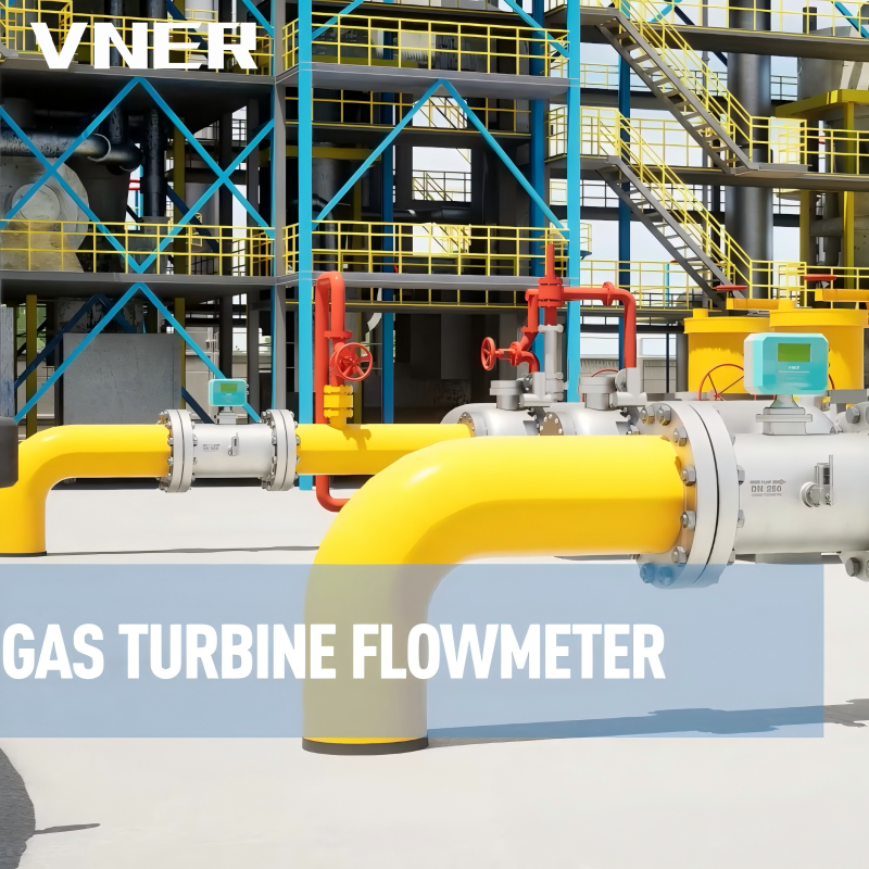 LWQ Series Gas Turbine Flowmeter for Stable Dry Gas FlowsEngineered for clean, dry gases under steady conditions, this turbine meter delivers repeatable volumetric readings with low pressure loss, and supports compensated flow when combined with temperature and pressure sensors.View Product →
For clean, dry gas flows at steady conditions, the LWQ gas turbine flow meter from VNER demonstrates the value of keeping the measurement simple: low pressure loss, repeatable volume readings, and minimal maintenance. When the process guarantees stable pressure and temperature, a single density value applied in the control system converts that volume reading to mass with acceptable accuracy for monitoring purposes. The key phrase is "stable conditions." The moment the gas supply pressure varies, the single-density conversion stops being valid.
Measuring Mass Directly with Coriolis Flow Meters
When the cost of a density error is high, the cleanest solution is to measure mass directly. The Coriolis flow meter is the industrial standard for direct mass measurement.
How a Coriolis Meter Works
A Coriolis meter contains one or two curved or straight tubes through which the fluid flows. The tubes are vibrated at their natural frequency by an electromagnetic driver. When fluid moves through a vibrating tube, it experiences a Coriolis acceleration, which distorts the tube oscillation in a way that is proportional to the mass flow rate. Sensors at two points on the tube detect this phase shift and translate it into a mass reading. The physics of the measurement does not depend on the fluid's density, temperature, pressure, or flow profile, which is what makes the technology inherently mass-based.
The same oscillation frequency also reveals the mass inside the tube, giving the meter a continuous density output as a byproduct. This density output is often accurate to a few tenths of a percent and can itself be used for concentration monitoring, for detecting a product change, or for converting the measured mass flow into a volumetric flow at line conditions.
Strengths and Limitations in Practice
The strengths of Coriolis meters explain their widespread use in custody transfer and critical process service: no moving parts, no upstream or downstream straight-run requirement, a wide turndown ratio, and typical accuracy of 0.1 to 0.2 percent of rate in well-applied industrial meters. They are equally at home with liquids, slurries, and dense gases.
The limitations are less about measurement and more about application: a Coriolis meter introduces a pressure drop because the flow is forced through a restriction; the cost rises steeply with line size; and the meter body must be properly supported to avoid transmitting external vibration into the measurement. In high-temperature services, careful specification of the flow tube material and the electronics is required.
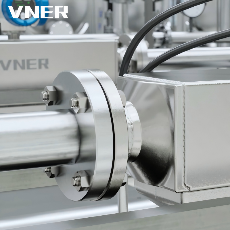 AC Series Coriolis Mass Flowmeter for Direct Mass and Density MeasurementThis Coriolis meter provides true mass flow, density, and temperature from one instrument, making it suitable for chemical dosing and process control where density assumptions fail.View Product →
The AC series Coriolis mass flow meter from VNER illustrates the practical shape of this technology in modern plants. It delivers a true mass reading, a density reading, and a temperature reading from a single instrument, and it is commonly specified for chemical dosing, process control, and fuel measurement applications where the density assumption is known to be false. A more detailed explanation of the measurement principle is available in this article on how Coriolis mass flow meters work.
For the engineer dealing with the steam-line discrepancy described at the start of this article, a Coriolis meter eliminates the problem at its source: no density is assumed, because none is needed for the mass calculation. If a volumetric number is later required for reporting, the meter's density output performs the reverse conversion. One instrument covers both directions of the mass-to-volume relationship.
Measuring Volume with Temperature and Pressure Compensation
Coriolis meters are economically justified for many applications, but not for all. A large water line, an extensive air distribution network, or a process where the required accuracy is a few percent does not need a mass meter costing many times more than the alternative. In those services, a volumetric meter plus a density calculation is the conventional solution.
The concept is straightforward: the meter measures volume, two or three transmitters measure the actual pressure and temperature at the meter, and a flow computer or control system calculates density from those values. For a gas, the calculation is:
ṁ = Q × P × M / (Z × R × T)
with P and T measured at the meter's location and converted to absolute units. For steam, the density comes from a steam-table formulation using the measured pressure for saturated steam, or pressure and temperature for superheated steam.
How good is this approach? With a well-maintained vortex or swirl meter, a pressure transmitter calibrated to better than 0.5 percent of span, a temperature probe with error below one kelvin, and a fluid composition that stays constant, the resulting mass flow uncertainty is typically in the range of 1.5 to 3 percent of reading. That is adequate for internal efficiency monitoring, allocation between process units, and most regulatory reporting. It is not adequate for fiscal custody transfer, where uncertainties on the order of 0.5 percent are commonly required.
The assumptions matter. The fluid must be single-phase and homogeneous: wet steam will break the density calculation completely. The pressure used in the calculation must be the pressure at the volumetric element, not at a tapping point fifty meters downstream past a control valve. The temperature sensor must be inserted to the correct depth. And the composition must be verified, because the molar mass M appears directly in the density formula.
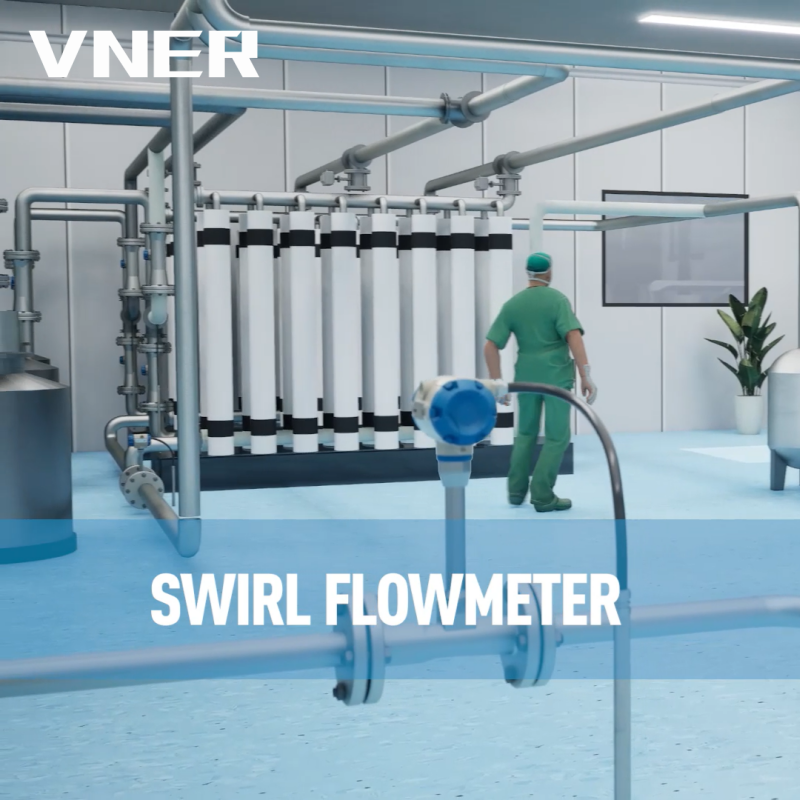 SA80T-TP Series Swirl Flowmeter with Integrated CompensationThis swirl flowmeter integrates temperature and pressure sensors in one body, enabling real-time density compensation for mass flow output in steam and compressed gas energy metering applications.View Product →
VNER addresses the integration challenge with its SA80TTP series temperature-pressure compensated swirl flow meter. The swirl meter measures volumetric flow through the precession of a vortex, and the SA80TTP variant adds an integrated pressure port and a temperature sensor in the same body, so the compensation calculation uses the actual process conditions at the measurement point. One instrument flanges into the line and delivers a compensated mass flow output without the usual patchwork of separately mounted transmitters and impulse lines. In services like saturated steam distribution and compressed gas networks, this type of meter has become the workhorse of plant energy accounting.
How to Choose: Direct Mass or Compensated Volume
The choice between measuring mass directly and measuring volume with compensation reduces to a small set of questions. Answering them before purchase prevents the two most common specification errors: buying a mass meter for a service that does not need it, and buying a plain volumetric meter for a service that does.
- What is the fluid, and how much can its density change across the operating envelope? Water at stable temperature: near zero risk. Saturated steam across 3 to 10 bar: enormous.
- What accuracy does the application actually require? A 5 percent tolerance for a boiler combustion-air monitor is different from a 0.3 percent requirement for product loading.
- What is the consequence of being wrong? Distorted reports and inefficiency are one thing; an undersized relief calculation or a rejected custody transfer is another.
- What is the total cost of ownership, including pressure loss, calibration, and maintenance, not just the purchase price?
| Criterion | Coriolis mass meter | Volumetric meter with T/P compensation |
|---|---|---|
| Measurement principle | Direct mass from Coriolis force | Volume from vortex, swirl, or turbine; density computed from T and P |
| Typical mass accuracy | 0.1-0.2% of rate | 1.5-3% of reading |
| Density handling | Measured continuously | Computed; composition must be fixed |
| Pressure drop | Moderate to high | Low to moderate |
| Straight-run requirement | None | Usually specified |
| Moving parts | None | Turbine: rotating; vortex and swirl: none |
| Best fitted service | Variable density, fiscal, process-critical | Stable gas/steam networks, monitoring |
| Cost profile | Higher first cost, low maintenance | Lower first cost, periodic T/P transmitter calibration |
Two additional criteria belong in the specification process. First, calibration capability: a mass meter is only as good as the calibration loop it was verified on. Second, engineering support: a vendor that sizes instruments on the basis of actual process data, rather than a catalog table, is considerably more likely to deliver a meter that meets its stated accuracy in service. VNER describes its engineering-driven sizing approach on its About page, and the practical value shows up in details such as selecting the right flow section, setting the low-flow cutoff, and specifying the correct density model for the compensation calculation.
Worked Examples: Converting Volume to Mass in Real Services
Numerical examples anchor the concepts. The following three cases represent the most common conversion tasks in plant practice.
Saturated Steam
A vortex meter on a saturated steam line reads 8,000 m3/h at 7 bar absolute. The saturation temperature is approximately 165 °C and the steam-table density is 3.67 kg/m3. The mass flow is 8,000 × 3.67 = 29,360 kg/h. If the plant had kept a fixed density of 2.16 kg/m3 from an earlier 4 bar operating point, the calculated mass flow would be 17,280 kg/h, understating the true mass by 41 percent. A steam balance built on that number would show a massive, impossible loss.
Natural Gas at Elevated Pressure
A DN100 meter run carries natural gas at 20 bar absolute and 25 °C. The average velocity is 10 m/s. The cross-sectional area is π × (0.1)² / 4 = 0.00785 m², so the volumetric flow is 10 × 0.00785 × 3,600 = 283 m3/h. With a molar mass of 17.2 kg/kmol, a compressibility factor Z of 0.92 at 20 bar and 25 °C, and the universal gas constant 8,314 J/(kmol·K), the density is (20 × 10⁵ × 17.2) / (0.92 × 8,314 × 298.15) ≈ 15.1 kg/m3. The mass flow is 283 × 15.1 = 4,273 kg/h. In normal cubic meters, that is 4,273 / 0.72 ≈ 5,900 Nm3/h. The mistake to avoid is multiplying the actual volume by the normal density: 283 × 0.72 = 204 kg/h, an error of more than 95 percent.
Liquid Hydrocarbon at Warm Temperature
A turbine meter measures 120 m3/h of diesel at 35 °C. The density at 15 °C is 840 kg/m3; at 35 °C it is approximately 824 kg/m3. The true mass flow is 120 × 824 = 98,880 kg/h. Using the fixed 15 °C density would give 100,800 kg/h, a 1.9 percent overstatement. Over a 10,000-tonne monthly transfer, that is roughly 190 tonnes of billing error in one direction or the other depending on which density the commercial contract requires.
Common Pitfalls That Show Up in Audits and Troubleshooting
Years of plant audits reveal the same conversion errors recurring across sites. Once you recognize them, they are easy to prevent.
- A fixed density programmed at commissioning and never revisited. The most frequent source of error in steam and gas services. Operating pressure creeps upward, fluid density follows, and the mass reading stays anchored to the old value.
- Gauge pressure used where absolute pressure is required. The density equation is built on absolute pressure. Using gauge pressure in a 7 bar process overstates density by roughly 14 percent because the atmospheric baseline is missing.
- Reference conditions mixed in reporting. Normal cubic meters (0 °C, 1.01325 bar) and standard cubic meters (15 °C or 20 °C) look similar on a DCS tag, but the difference between them is about 5 percent in mass for the same numerical value.
- Pressure measured at the wrong location. When the transmitter is downstream of a control valve or a strainer, the density calculation uses a pressure that does not represent the fluid at the meter element.
- Composition drift ignored. Biogas, digester gas, and refinery fuel gas change composition over time. A fixed molar mass in the density calculation silently distorts the mass flow.
- Wet steam treated as saturated steam. Steam with 90 percent quality has roughly 10 percent lower density than pure saturated steam at the same pressure. Using the pure-steam table value overstates the mass flow by about 10 percent.
- The compressibility factor Z omitted at elevated pressure. At 60 bar, most hydrocarbon gases have Z values between 0.85 and 0.92. Setting Z equal to 1 adds 8 to 15 percent of error on top of every other calculation.
Each of these pitfalls shares a common root: the engineer who set up the calculation assumed that density does not change. The fix is to treat density as a live variable and to verify it periodically.
A Field-Proven Method for Getting the Conversion Right
Convert these concepts into a repeatable working procedure. The following sequence has been tested in commissioning, troubleshooting, and audit work across dozens of plants.
- Establish what the instrument actually outputs. Read the meter tag, the manual, and the DCS configuration. Some meters labeled "flow" output volume; others output mass; some output both. Confirm before doing any mathematics.
- Define the fluid state at the meter. Record the temperature, the absolute pressure at the meter element, the phase, and the composition at the time of verification.
- Select a density source matched to the fluid. For a liquid at stable temperature, a density table is enough. For a gas, use the equation of state with a realistic Z factor. For steam, use an approved steam-table formulation with measured pressure or temperature.
- Convert and cross-check. Multiply the volumetric flow by the selected density to obtain the mass flow. Where possible, compare the result against a plant-level mass balance, a weigh scale, or a second instrument of different principle.
- Automate the conversion. Manual conversions in spreadsheets introduce transcription errors and are rarely repeated at the proper frequency. Put the density calculation in the flow computer or DCS with live pressure and temperature inputs.
- Report in the unit the business needs. Mass for material balance, normal volume for gas contracts, actual volume for pipeline capacity. State the reference condition next to the number.
- Re-verify at intervals. Calibrate the pressure and temperature transmitters on the same schedule as the flow meter itself. A compensated volumetric system is only as accurate as its least accurate input.
For a stable-density liquid with a modest accuracy target, steps 3 and 4 take minutes. For a gas or steam network with variable conditions, the same steps justify the investment in compensation hardware, or in a direct mass meter that removes the density problem entirely.
Return once more to the two meters on the steam line. The plant could have handled that discrepancy in three ways: recalibrate the vortex meter and re-enter its fixed density, which is a short-term patch; install pressure and temperature compensation on the volumetric meter, which is a durable solution for monitoring-grade accuracy; or replace it with a Coriolis mass meter, which is the definitive solution when mass accuracy is critical. All three are legitimate engineering responses. The correct one depends on the purpose of the measurement.
That is the central idea of this article. The conversion from mass flow rate to volumetric flow rate is one multiplication, and the reverse is one division. The difficulty is not the arithmetic; it is the density. A process engineer who knows the actual density at the meter, who understands how pressure, temperature, and composition move that density, and who has selected an instrument that either measures mass directly or supplies the data to reconstruct it, will produce trustworthy numbers day after day. The instruments available today have excellent diagnostics, but they cannot compensate for a concept that was wrong on the day it was configured.
VNER manufactures both families of instruments, from the AC series Coriolis mass flow meters to compensated swirl and vortex meters, and its engineers routinely help EPC contractors, plant operators, and OEMs decide which approach fits a given process. The decision starts, as it should, with a single question about the plant: what does this process need to know, mass or volume?


Products
Contact Information
-

+86 18652789521
+86-0514-83633600 / 83633900 -

+86-0514-83633600 / 83633900
-

s@vner.com.cn
katherine@vner.com.cn -

No. 11 Xingye Road, Chenji Town Industrial Park, Yizheng, Yangzhou, China
