
 0
0
 EN
EN  English
 عربى
عربى Español
 русский
If you need any help, please feel free to contact us
Home / News / Industry News / Flow Rate Equation in Process Industries: From Q=Av to Meter Selection
Flow Rate Equation in Process Industries: From Q=Av to Meter Selection
If you are sizing a flowmeter for a 10-inch steam line, a slurry line that keeps blocking, or a custody transfer skid, the flow rate equation is not a textbook exercise. The real question is whether the equation you rely on remains valid under the actual process conditions. That single question determines whether you get a stable, repeatable measurement or years of maintenance problems.
For more than a decade, Jiangsu Vner Electronic Technology has worked with EPC contractors, end users, and OEM partners on these exact problems. Our starting point is always the same: the flow rate equation is the foundation of instrument selection, but it only becomes useful when you translate it into the physics your meter will face. This article explains how to do that translation.
The Flow Rate Equation You Already Know
The basic flow rate equation is Q = A × v. Q is the volumetric flow rate in cubic meters per second, A is the cross-sectional area of the pipe in square meters, and v is the average flow velocity in meters per second. For a circular pipe, A = π × D² / 4, where D is the internal diameter.
This equation is more than a formula. It defines the relationship between pipe size, velocity, and the volume of fluid passing a given point. It also sets the constraints for every velocity-based flowmeter you will ever specify.
Why the Continuity Equation Matters
For an incompressible fluid, continuity gives us A₁v₁ = A₂v₂. If you reduce the pipe diameter, velocity increases. If you expand it, velocity drops. This is why a flowmeter installed in a reducer or a partially full pipe will not read the same as in a straight run. The equation assumes full cross-sectional area and a developed velocity profile.
In practice, a velocity flowmeter needs enough straight pipe before and after the meter to let the profile stabilize. The tolerance is often 10D upstream and 5D downstream, but that is merely a rule. The real number depends on fittings, valves, and the Reynolds number. EPC engineers sometimes treat this as a conservative default; instrumentation engineers know that a double elbow or a control valve close to the meter can shift the accuracy by several percent.
Volumetric Flow Rate and Mass Flow Rate Are Not Interchangeable
If you need mass flow, the equation becomes ṁ = ρ × A × v, where ρ is the fluid density. This distinction separates two fundamentally different measurements. Volumetric flow rate tells you how much volume passes, but it says nothing about the mass that matters for combustion, heat transfer, custody transfer, or chemical reactions.
For liquids, density is generally stable. For gases and steam, however, density changes with temperature and pressure. A volumetric flow reading at 10 bar will represent a very different mass rate than the same reading at 2 bar. This is why gas flowmeters often require temperature and pressure compensation or direct mass flow measurement.
The practical consequence for buyers is simple. If your process purpose is energy balance or material balance, specify a meter that delivers mass flow. That means either a Coriolis mass flowmeter or a volumetric meter with compensated density. Relying on a raw volumetric signal in a variable pressure application is a common source of discrepancy between the plant metering system and the actual process.
How Industrial Flow Meters Use or Challenge the Flow Rate Equation
Every velocity-based flowmeter is designed around the same relationship: measured variable → velocity → Q = A × v. The difference between technologies lies in how they measure velocity.
Electromagnetic Flowmeters
An electromagnetic flowmeter uses Faraday's law of induction. A conductive fluid moving through a magnetic field generates a voltage proportional to velocity. Since the pipe area is fixed, the meter converts that voltage into a volumetric flow rate. This works well for water, wastewater, and many chemical slurries. It requires the fluid to have sufficient conductivity and a fully filled pipe.
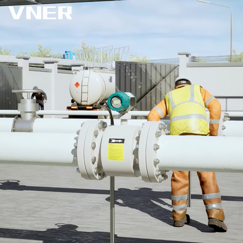 LDG Economy General-Purpose Electromagnetic Flowmeter for Conductive LiquidsA cost-effective magmeter based on Faraday's law, ideal for water, wastewater, and chemical slurries. It features no moving parts and negligible pressure loss, providing stable volumetric flow measurement for plant inlet and cooling water monitoring.View Product →
Vortex Flowmeters
A vortex flowmeter measures the frequency of vortices shed from a bluff body. The frequency is proportional to velocity, so Q = f / K. This technology is common for steam, gases, and low-viscosity liquids. It is sensitive to the Reynolds number range and requires enough straight pipe. Vortex meters are popular in energy plants because they have no moving parts and can handle high temperatures when paired with the right sensor.
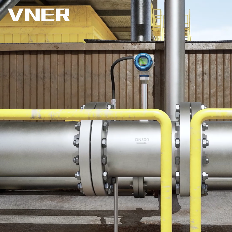 MA80T-TP Vortex Flowmeter with Temperature and Pressure CompensationDesigned for steam and gases, this vortex meter integrates RTD and pressure input to correct density in real time, delivering mass flow and standard volume outputs. Ideal for energy balance and cost allocation in utility networks.View Product →
Coriolis Mass Flowmeters
Coriolis meters measure mass flow directly by tracking the phase shift of vibrating measuring tubes. Since they do not need to convert from volumetric to mass, they are less affected by density changes. They are the benchmark for custody transfer and critical chemical processes.
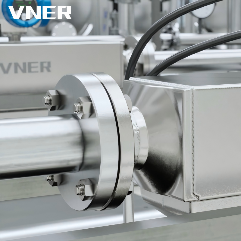 AC Series Coriolis Mass Flowmeter for Direct Mass and Density MeasurementUtilizing the Coriolis effect, this meter directly measures mass flow, density, and temperature with high precision. Suited for custody transfer and critical processes where mass-based accuracy is essential, including blending and chemical injection applications.View Product →
Understanding this distinction matters because a meter that is accurate as a volumetric device may be completely unsuitable for a mass-based application. This is the first filter in any flowmeter selection.
Selecting the Right Flow Rate Equation for Your Process
The correct flow rate equation is not only about the formula; it is about matching the meter to the fluid and the process. The table below gives an immediate overview of what to expect from each technology.
| Technology | Measured Quantity | Equation Relevance | Typical Limitations |
|---|---|---|---|
| Electromagnetic | Volumetric flow rate | Q = A × v via Faraday voltage | Requires conductive liquid, full pipe |
| Vortex | Volumetric flow rate | Q = f / K | Requires adequate Reynolds number, straight pipe |
| Coriolis | Mass flow rate | ṁ measured directly, no density assumption | Pressure drop, higher cost, sensitivity to vibration |
For conductive liquids such as water, wastewater, and most acid or alkali solutions, an electromagnetic flowmeter is usually the most robust choice. It has no moving parts, no obstruction, and its accuracy does not depend on viscosity. The main risk is incomplete filling. If the pipe is not full, the area used in Q = A × v is no longer the actual wetted area, and the reading will be wrong.
For gases and steam, a vortex meter is often selected because it works over a wide range of flow rates without moving parts. The caveat is that the meter must be sized for actual operating velocity, not standard or normal conditions. A low-flow application may fall below the meter's minimum Reynolds number, causing erratic pulse output.
When the mass balance matters, Coriolis flowmeters take the lead. They deliver a direct mass reading, which is why they are used in custody transfer, loading systems, and chemical injection. They also give the operator a quick view of density, which helps detect process upsets. The cost is higher pressure drop and a weight that must be properly supported.
Real-World Errors That Change the Flow Rate Equation
Even after you select the right meter, installation details can twist the expected behavior. The most common errors we see in field audits are related to the assumptions hidden in Q = A × v.
- Short straight run: A valve or elbow upstream creates swirl and a skewed velocity profile. The meter still reports a number, but it is not the average velocity.
- Gas bubbles in liquid: In an electromagnetic meter, air bubbles cause spikes and signal instability. In a Coriolis meter, entrained gas changes the effective mass and damping, requiring proper diagnostics.
- Partially filled pipes: This is critical for gravity-fed lines. The flowing cross-section is smaller than the pipe area, so the equation's A is no longer correct.
- Low flow at low density: Gas and steam at low velocity can produce a weak vortex signal. The meter may drop below its functional threshold, and linearity degrades.
- Vibration: Vortex meters and Coriolis meters are both sensitive to mechanical vibration. Mounting brackets and process piping must isolate the meter from nearby pumps and compressors.
- Calibration drift: Even the best meter will drift. The question is whether you have an in-house calibration capability or a trusted partner to re-verify the meter periodically.
These errors are not exotic. They occur in ordinary plants every day. The difference between a project that works and one that fights process control is how carefully these factors are addressed before the meter is purchased.
A Buyer's Checklist for Flow Meter Applications
When you sit down to specify a flowmeter, work through this list in the same order. It starts with the equation and ends with the supplier's engineering experience.
- Define the measured value. Is it volumetric flow or mass flow? If mass balance or energy balance is the goal, pick a mass-based meter or plan for density compensation.
- Understand fluid properties. Conductivity, viscosity, density, temperature, pressure, and whether the fluid is a liquid, gas, or slurry. These properties decide which technology can survive.
- Check the installation envelope. Can you provide the required straight pipe? Is the pipe always full? Is vibration present? A meter that cannot be installed correctly will never deliver its stated accuracy.
- Calculate realistic velocity. Use A = πD²/4 and your design flow to find v. Then check that this falls within the selected meter's operating range, not just at maximum design but also at turndown.
- Consider pressure loss. If the meter creates a high permanent loss, your pump or compressor may need to be larger. This is a real cost that should be in the purchasing decision.
- Review maintenance access. Can you isolate the meter? Can you remove the sensor without draining the line? This affects plant uptime.
- Ask about calibration. A manufacturer that has in-house calibration facilities and a certified quality process gives you more confidence in the baseline. At VNER, in-house calibration is a core part of our production flow.
You may also want to understand how the supplier services projects across different industries. If you are in oil and gas, petrochemical, polysilicon, power, or water and wastewater, the same flow rate equation behaves differently in each. This is why industry-specific experience is a practical advantage when a manufacturer has delivered hundreds of project-based installations.
The flow rate equation is where good measurement starts, but it is never the whole story. The formula becomes reliable only after you match the meter to the fluid, the pipe, the process, and the purpose. A meter that works in theory can fail in the field when the assumptions behind Q = A × v are not met.
At Jiangsu Vner Electronic Technology, we follow an engineering-driven sizing and selection approach. That means we look at your process data, calculate the real velocity and mass flow, and only then propose a meter from our range. If you are facing a difficult flow application, the equation is the right place to start. Knowing what to do with it is what gets you a measurement you can trust for years.


Products
Contact Information
-

+86 18652789521
+86-0514-83633600 / 83633900 -

+86-0514-83633600 / 83633900
-

s@vner.com.cn
katherine@vner.com.cn -

No. 11 Xingye Road, Chenji Town Industrial Park, Yizheng, Yangzhou, China
