
 0
0
 EN
EN  English
 عربى
عربى Español
 русский
If you need any help, please feel free to contact us
Home / News / Industry News / Volumetric Flow Rate Equation: Calculations, Units, and Real-World Measurement
Volumetric Flow Rate Equation: Calculations, Units, and Real-World Measurement
An engineer at a potable water treatment plant once saw the flow indication from a magnetic flowmeter and a clamp-on ultrasonic meter disagree by more than 10 percent. The immediate assumption was that one instrument was faulty. After a closer look, the root cause was not a sensor problem. The two meters were using different reference conditions. One reported the actual volume of water moving through the pipe at operating temperature; the other displayed a normalized value at 20 °C. The gap between the readings was not a hardware failure but a units and reference-condition mismatch. The volumetric flow rate equation is compact in form, but it carries implications that extend far beyond the formula. Whether you are sizing a pump, checking a carbon balance, or selecting a custody transfer meter, the definition of volumetric flow rate and the way it is measured determine the accuracy of every downstream decision.
The Volumetric Flow Rate Equation: Core Concepts and Definitions
Volumetric flow rate is the volume of fluid that passes through a given cross-sectional area per unit time. In mathematical form, it is written as Q = V / t, where Q is the volumetric flow rate, V is the volume, and t is the time interval. This definition is straightforward, but it is not the form most engineers use on the job. The practical equation is Q = A × v.
In this equation, A is the cross-sectional area of the pipe, duct, or channel, and v is the average velocity of the fluid across that area. The product of area and velocity gives the volume passing per unit time. The equation is valid for any fluid, whether liquid or gas, and it forms the basis for much of flow instrumentation.
Why the Equation Matters in Process Control
Volumetric flow rate is often the first variable measured when engineers want to understand how much material is moving through a line. It is used to control chemical dosing, monitor water consumption, balance gas flows, and determine the performance of pumps and compressors. The equation itself is simple, but it can produce misleading results if the area or the velocity is not correctly defined.
Common Units and Conversions
The SI unit of volumetric flow rate is cubic meters per second (m3/s). In industrial practice, cubic meters per hour (m3/h) is more common. In the United States, gallons per minute (GPM) and cubic feet per minute (CFM) are standard. For gases, engineers often use normal cubic meters per hour (Nm3/h) or standard liters per minute (SLPM). Each unit implies a certain reference condition.
When converting between units, be careful with time and volume dimensions. For example, 1 m3/s = 1000 L/s = 60000 L/min = 3600 m3/h. A decimal error in conversion can change a result by a factor of 60. It is always worth writing out the conversion and checking that the time and volume units cancel correctly.
Continuity Equation and Conservation of Volume
For steady, incompressible flow, the law of conservation of mass simplifies to conservation of volume. In a pipe of varying diameter, the volumetric flow rate is the same at every cross-section. This is the continuity equation: A1 × v1 = A2 × v2.
This has a practical consequence. If a pipe is reduced from a 100 mm ID to a 50 mm ID, the velocity will increase by a factor of four to keep the same volumetric flow rate. A flow meter installed in the smaller section will see a much higher velocity, which can create higher pressure drop and more noise. Understanding the continuity equation helps engineers choose the correct pipe size and flow meter location.
Calculating Volumetric Flow Rate: Derivation, Assumptions, and Worked Examples
The equation Q = A × v is derived by integrating the velocity profile over the cross-sectional area. For a uniform velocity, Q = A × v exactly. Real pipes have velocity profiles that are not flat; they are higher at the center and lower near the wall. The average velocity is defined as Q/A. So the equation is a definitional identity when the average velocity is used.
The basic assumptions are steady flow, an incompressible fluid, and a fully filled cross-section. For gases, the density changes along the pipe, but the volumetric flow rate at a given point is still defined as Q = A × v at that point. This is why a gas flow meter should be installed where the pressure and temperature are known or measured.
Velocity Profiles in Real Pipes
In a fully developed turbulent flow, the velocity profile is blunt; the centerline velocity is about 1.2 to 1.3 times the average velocity. In laminar flow, the profile is parabolic, and the centerline velocity is 2 times the average velocity. Most flowmeters are calibrated to read the average velocity, but they require a sufficiently developed profile. If a meter is installed too close to an elbow or valve, the profile can be distorted, and the reading may be off.
Worked Example: DN80 Pipe with 3.5 m/s Flow
Take a concrete example. Consider a DN80 pipe with an inner diameter of 80 mm. The area A = π × d2/4 = 3.1416 × (0.08 m)2/4 = 0.00503 m2. The flow velocity is 3.5 m/s. Then Q = 0.00503 × 3.5 = 0.0176 m3/s. Convert to m3/h: 0.0176 × 3600 = 63.4 m3/h. If the fluid is water at 20 °C and a density of 998 kg/m3, the mass flow rate is 63.4 m3/h × 998 kg/m3 = 63273 kg/h = 63.3 tons/h.
This type of calculation is common in pump sizing. The pump must be selected to deliver the required volumetric flow rate against the system head. The flow rate also determines the Reynolds number, which affects the pressure drop and the flow regime.
Unit Conversion Table for Volumetric Flow Rate
| From | To | Multiply by |
|---|---|---|
| m3/s | m3/h | 3600 |
| m3/h | L/min | 16.667 |
| m3/h | GPM | 4.403 |
| CFM | m3/h | 1.699 |
Keep in mind that these conversions are for actual volume at the same conditions. They do not account for changes in density.
Volumetric Flow Rate vs. Mass Flow Rate: Why Density Matters
Mass flow rate is the mass of fluid per unit time and is often written as ṁ. It relates to volumetric flow rate by ṁ = ρ × Q, where ρ is the fluid density at the flow conditions. In process industries, mass flow is important for energy balances, reactions, and custody transfer. Volume is important for pipe sizing and pump selection.
Liquids are often treated as incompressible, but density changes with temperature are not negligible. Water at 4 °C has a density near 1000 kg/m3; at 80 °C, its density drops to about 971.8 kg/m3. This is a change of about 3%. If a process expects a fixed mass flow rate and a flowmeter reads volume, the mass flow calculation will be off if the temperature is not accounted for.
Gases are highly compressible. A 10% change in absolute pressure can change density by 10% if the temperature is constant. Standard conditions are used to normalize gas flow. The conversion from actual volumetric flow to standard volumetric flow requires the density ratio. The formula is Q_std = Q_actual × (ρ_actual / ρ_std).
Why Standard Reference Conditions Matter
Different industries use different reference conditions, such as 0 °C and 101.325 kPa, or 20 °C and 101.325 kPa. A flowmeter that displays standard cubic meters per hour is already performing a density correction. A raw volumetric flowmeter with no compensation will not reflect the mass of gas passing through the pipe. This is a common source of confusion when a meter shows one number and the process calculations expect another.
For processes where density is not constant, a Coriolis mass flowmeter offers a distinct advantage because it measures mass flow and density in a single instrument.
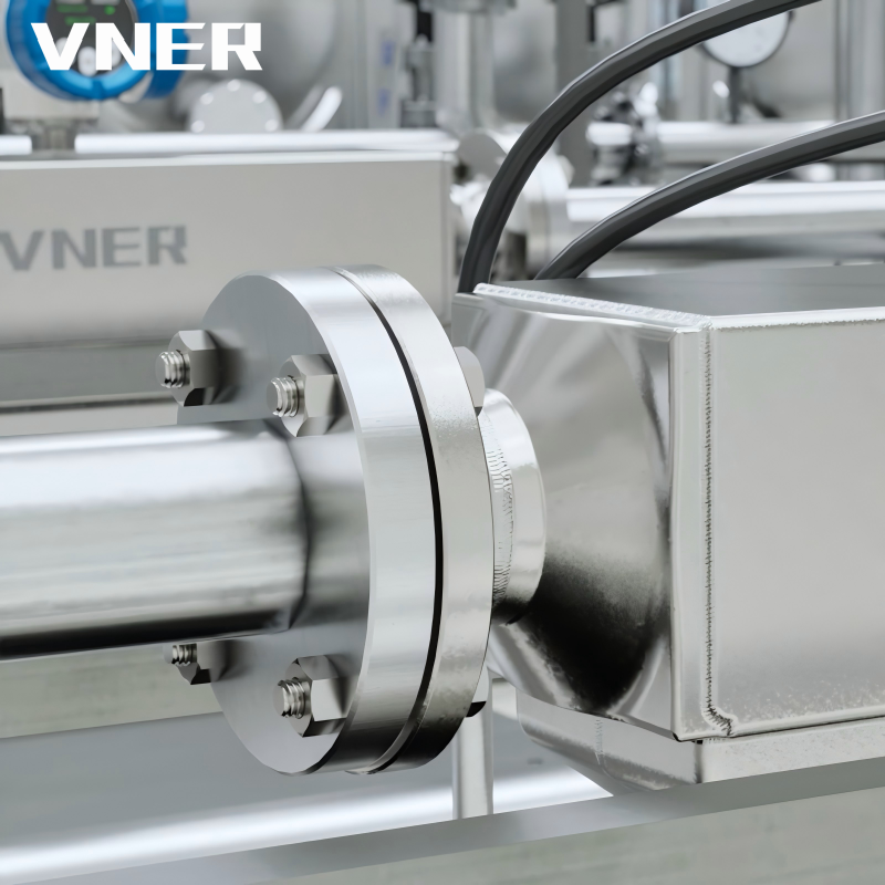 AC Series Coriolis Mass Flowmeter for Direct Mass Flow and Density MeasurementThe AC Series measures mass flow, density, and temperature directly based on the Coriolis effect, making it ideal for processes where density varies. It derives volumetric flow in real time, suitable for custody transfer and critical control applications.View Product →
How Industrial Flow Meters Measure Volumetric Flow Rate
The equation Q = A × v is used in different ways by different flowmeter technologies. Some infer Q from a velocity measurement, others capture a known volume. The following is a practical overview of the main technologies and how they relate to volumetric flow rate.
Differential Pressure Flow Meters
These meters generate a pressure drop across a primary element such as an orifice plate. The volumetric flow rate is proportional to the square root of the differential pressure. The basic formula is Q = K × sqrt(ΔP / ρ). The value of K depends on geometry, Reynolds number, and the ratio of the orifice diameter to pipe diameter. Because density appears in the equation, changes in fluid density affect the reading. In gas applications, temperature and pressure compensation must be applied. Standards like ISO 5167 define the required geometry and installation conditions.
Vortex Flow Meters
A vortex flowmeter uses a bluff body inserted in the pipe to generate alternating vortices. The frequency of vortex shedding is proportional to the average fluid velocity. The Strouhal number is used to relate the frequency to velocity. The advantage is that the frequency is essentially independent of density, making vortex meters useful for both liquids and gases. The main limitation is the need for a minimum Reynolds number, typically above 10,000 for reliable operation, and a sufficiently developed velocity profile. They also require a certain amount of straight pipe upstream and downstream.
For process steam and gas flows, vortex flowmeters are a common choice because they have no moving parts and provide a reliable volumetric flow signal.
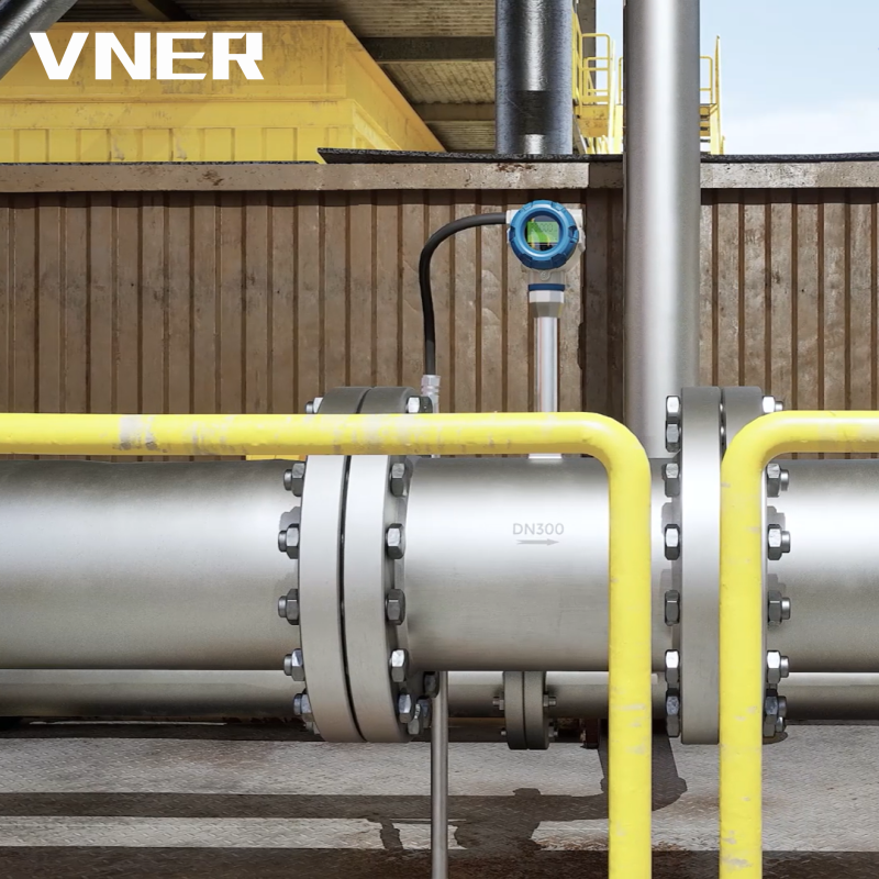 MA80T-TP Vortex Flowmeter with Temperature and Pressure CompensationThis vortex flowmeter integrates temperature and pressure measurement to provide compensated mass and standard volume flow, essential for steam and compressed gas networks where density changes affect accurate energy metering and cost allocation.View Product →
Electromagnetic Flow Meters
Electromagnetic flowmeters work on Faraday's law. When a conductive fluid flows through a magnetic field, a voltage is induced that is proportional to the average velocity. The meter requires the fluid to have minimum conductivity, usually above 5 microSiemens per centimeter. They are widely used in water, wastewater, and chemical slurries because they have no moving parts and do not obstruct flow. The velocity is measured directly, and the volumetric flow rate is computed from the pipe area.
Because electromagnetic meters measure velocity directly, they produce a true volumetric flow in the pipe under the existing temperature and pressure conditions. If the fluid is not conductive, another technology should be considered.
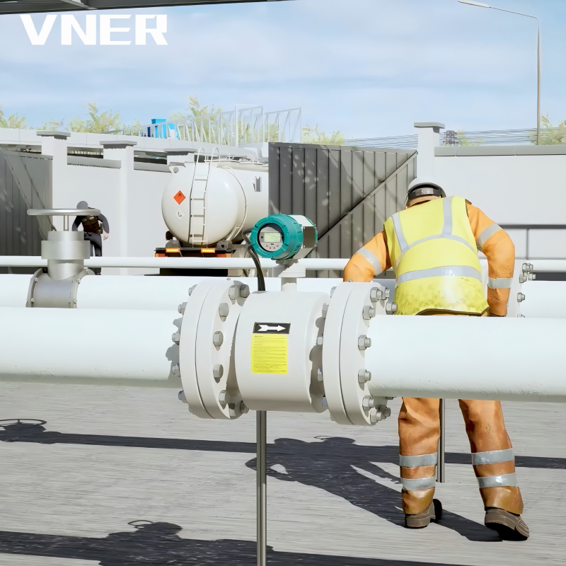 LDG Economy Electromagnetic Flowmeter for Conductive LiquidsThe LDG is a cost-effective magmeter for conductive liquids above 5 μS/cm, with no moving parts and negligible pressure loss. It suits water, wastewater, and chemical slurries, providing stable volumetric flow for general industrial monitoring.View Product →
Positive Displacement Flow Meters
Positive displacement meters capture discrete volumes of fluid in rotating pockets. The flow rate is proportional to the number of revolutions. They are very accurate for liquids, but they have moving parts and can be sensitive to wear and sticking if the fluid contains particles.
Ultrasonic Flow Meters
Ultrasonic meters use sound waves to measure velocity. Transit-time meters measure the difference in sound travel time in the direction of flow and against the flow. Doppler meters rely on reflections from particles. They are non-intrusive and can be clamp-on, but they require clean fluids or specific particle conditions.
Coriolis Mass Flow Meters
Coriolis meters measure the mass flow directly by observing the phase shift in a vibrating tube. They also measure density, so they can provide a good estimate of volumetric flow. They are used for high-accuracy custody transfer and for fluids that are difficult to measure with other technologies.
Engineering Considerations for Selecting a Volumetric Flow Rate Meter
When buying a flowmeter, a solid understanding of the volumetric flow rate equation contributes to correct selection. The following factors are critical.
Fluid Properties
Start with the fluid. Is it conductive? Is it clean? Are there solids? What is the viscosity? What is the density variability? For non-conductive liquids and gases, a magnetic flowmeter is not an option. For dirty fluids, a positive displacement meter may not be appropriate. For high-temperature steam, a vortex flowmeter works.
Temperature and Pressure Compensation
For gases and steam, the volumetric flow rate at actual conditions is highly dependent on temperature and pressure. Without compensation, a meter can produce accurate actual-volume readings but the mass flow calculation will be wrong. Some meters have built-in temperature and pressure sensors to compute standard flow. When selecting a meter, ask whether the manufacturer offers an integrated density-compensation package.
Accuracy, Repeatability, and Turndown
Financial impact: A flowmeter with ±0.5% error may be fine for process control, but custody transfer may require ±0.1% or better. Repeatability is often more important than absolute accuracy for process control. The turndown ratio also matters. For example, a vortex meter may have a turndown of 30:1, while a Coriolis meter may achieve 100:1. The operating range should match the expected flow extremes.
Pressure Drop and Maintenance
Every flow element creates some pressure drop. A differential pressure device can have a high permanent pressure loss. An electromagnetic meter has almost no pressure loss. Higher pressure drop means higher pumping costs. Maintenance requirements also differ: moving parts in positive displacement and turbine meters need periodic maintenance; no moving parts in vortex, electromagnetic, or ultrasonic means lower maintenance.
Installation Requirements
Many flowmeters require straight pipe sections. For vortex flowmeters, typical requirements are 10D upstream and 5D downstream. For electromagnetic meters, requirements may be slightly less but still important. If the meter is installed with insufficient straight run, the velocity profile may be distorted and the reading unreliable.
Calibration and Life-Cycle Cost
The best flowmeters are calibrated against traceable standards. A manufacturer with in-house calibration facilities can offer a more reliable calibration process. The total life-cycle cost includes the initial purchase, installation, maintenance, downtime, and the cost of measurement errors. Choosing a meter that is too cheap can lead to significant long-term losses.
| Technology | Typical Accuracy | Turndown | Pressure Loss | Moving Parts |
|---|---|---|---|---|
| Orifice plate | ±1-2% | 4:1 | Medium-high | None |
| Vortex | ±0.5-1% | 30:1 | Low-medium | None |
| Electromagnetic | ±0.2-0.5% | 100:1 | Low | None |
| Coriolis | ±0.1-0.2% | 100:1 | Medium | None |
Common Mistakes When Using Volumetric Flow Rate Calculations
Even with a correct understanding of Q = A × v, errors in field application are common. The following mistakes can lead to wasted energy, off-spec product, or disputes in custody transfer.
Mistake 1: Ignoring density in gas measurement. A flowmeter that reports actual volume will produce lower numbers at standard conditions than expected if the gas pressure is high. If the mass balance relies on standard volume, this error is systematic.
Mistake 2: Mixing actual volumetric flow with standard volumetric flow. A value in Nm3/h is not the same as m3/h. The difference can be a factor of 10 at high pressure. Always confirm the reference conditions on the data sheet.
Mistake 3: Installing a meter with insufficient straight run. Elbows and valves distort the velocity profile. This can cause a flowmeter to over-read or under-read because the local velocity at the sensor is not the true average.
Mistake 4: Choosing a turndown that does not match the process. A meter with a narrow turndown can become inaccurate at low flow, and a meter designed for low flow can be saturated at high flow. The flow range should be verified against the process minimum and maximum.
Mistake 5: Using the wrong average velocity assumption. Some flowmeters are calibrated for a specific pipe schedule. Replacing the pipe with a different wall thickness changes the inner diameter and therefore the area calculation. A small change in diameter can produce a 2% offset in the flow rate.
Mistake 6: Not accounting for temperature and pressure changes in density. In a gas line that experiences diurnal temperature swings, the actual volumetric flow can change by 5% or more even when the mass flow is constant. If the process control uses the volume signal without density correction, the control loop will see false fluctuations.
Real-World Applications in Process Industries
The volumetric flow rate equation appears in every type of process plant, but the required measurement method depends on the fluid and the duty.
Water and wastewater treatment. Municipal water plants commonly use electromagnetic flowmeters because the water is conductive and the meter has no moving parts. The flow is used to control chlorine dosing and to measure plant inflow. A volumetric flowmeter with a low pressure loss is preferred to minimize pumping costs.
Oil and gas. Gas transmission and production facilities need accurate flow measurement for custody transfer. A Coriolis mass flowmeter or a vortex flowmeter with temperature-pressure compensation is typical. The standard calculation includes density correction to convert actual volume to standard volume. Mistakes here can lead to significant financial loss.
Chemical and petrochemical. Chemical dosing often involves aggressive liquids or slurries. Electromagnetic and Coriolis meters are used for conductive and high-accuracy applications. The key is to match the wetted materials with the fluid chemistry.
Power generation. Steam flow is commonly measured with vortex flowmeters because the vortex frequency is density independent and the meter can handle high temperatures. Boiler feedwater flow is often measured with differential pressure devices or Coriolis meters.
Semiconductor and polysilicon. Ultra-pure chemical liquids are dosed in small amounts. Mass flow control is preferred because the process recipe is based on mass, but the volumetric flow equation is still used to size lines and check velocities.
Conclusion: Putting the Volumetric Flow Rate Equation to Work
The volumetric flow rate equation Q = A × v is a tool, not a solution by itself. It tells you how much volume is moving through a pipe if you know the area and the velocity, but it does not tell you whether the volume is the number you need for your process. Temperature, pressure, density, velocity profile, and instrument calibration all influence the final result.
Selecting the wrong flowmeter can cost much more than the instrument. The right approach is to combine a solid understanding of the equation with an engineering-driven sizing process. VNER has more than a decade of experience in flow measurement for industrial process applications and invests in in-house calibration and certified quality processes. Explore how these principles are applied in specific industries and how a manufacturer's engineering practices can reduce your measurement risk.


Products
Contact Information
-

+86 18652789521
+86-0514-83633600 / 83633900 -

+86-0514-83633600 / 83633900
-

s@vner.com.cn
katherine@vner.com.cn -

No. 11 Xingye Road, Chenji Town Industrial Park, Yizheng, Yangzhou, China
