 English
 عربى
عربى Español
 русский
If you need any help, please feel free to contact us
Home / News / Industry News / Why Does a Vortex Flowmeter Become Unstable — or Even Stop Working — After Installation?
Why Does a Vortex Flowmeter Become Unstable — or Even Stop Working — After Installation?
Have you ever experienced a vortex flowmeter that shows poor accuracy, large signal fluctuations, or even complete signal loss after installation?
In many cases, the root cause is not the instrument itself, but rather improper sizing and installation practices. Vortex flowmeters are highly sensitive to velocity profile, flow regime, and piping configuration. Small deviations in these details can lead to significant measurement errors.
This article explains the key engineering principles behind proper sizing, reducer selection, and straight pipe requirements, based on industry standards and verified experimental research.
1.Meter Sizing for Wide Turndown Ratio: Why Diameter Reduction Is Often Necessary
To achieve a wide turndown ratio and ensure sufficient signal strength at low flow rates, it is common engineering practice to reduce the flowmeter diameter relative to the pipeline in order to increase fluid velocity.
For velocity-profile-dependent flowmeters—such as:
- Vortex flowmeters
- Swirl (vortex precession) flowmeters
- Electromagnetic flowmeters
this diameter matching is typically achieved using concentric reducers.
General Sizing Principle
- In most applications, the flowmeter nominal diameter should be equal to or smaller than the pipe diameter.
- For vortex flowmeters, the calculated meter size is often one to two nominal sizes smaller than the pipeline.
Example
- Pipeline: 8" (DN200)
- Vortex flowmeter: 4" (DN100)
In special cases—such as oil custody transfer or low-flow nitrogen measurement—even larger reductions may be applied to satisfy extreme turndown requirements.
However, oversizing remains a frequent problem. In several projects, vortex flowmeters were selected too large, resulting in:
- Insufficient velocity during normal operation
- Operation outside the effective measuring range
- Severe signal instability after commissioning
Case note:
For nitrogen service with a 4" pipeline selected for start-up demand, installing a 1/2" vortex flowmeter represents an extreme reduction. Both the pipeline sizing logic and the meter selection require careful revaluation.
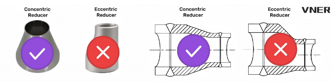
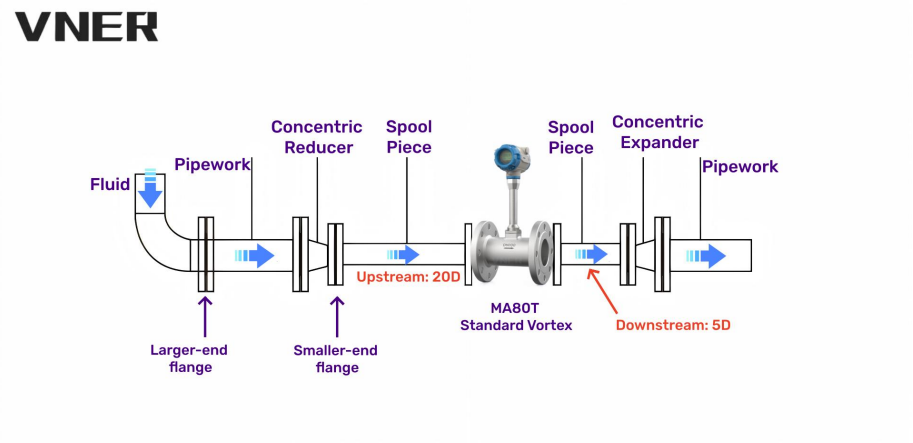
2.Reducer Selection: Always Use Concentric Reducers
Whenever pipe diameter reduction or expansion is required in vortex flowmeter installations:
Concentric reducers must be used.
Eccentric reducers create asymmetric velocity profiles that significantly degrade measurement accuracy in velocity-sensitive instruments.
3.Straight Pipe Requirements for Reduced-Diameter Installations
Reducer Geometry Requirements
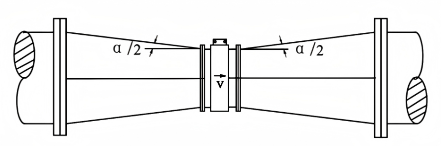
To minimize flow distortion:
- The cone angle α of the reducer should not exceed 15°
- Under this condition, the reducer can be treated as part of the straight pipe length
Both upstream and downstream reducers must be concentric, gradual reducers.
4.Minimum Upstream Straight Length Requirements (Typical Values)
|
Upstream Disturbance Type |
General Required Straight Length |
| No disturbance |
15D |
|
Concentric reducer |
15D |
|
Concentric expander |
18D |
|
Single 90° elbow |
20D |
|
Two 90° elbows (same plane) |
25D |
|
Two 90° elbows (different planes) |
40D |
|
Valve |
50D |
D = internal pipe diameter
5.General Installation Conditions for Vortex Flowmeters
A properly installed vortex flowmeter should meet the following conditions:
a) Installed horizontally or vertically (for liquids: bottom-to-top flow direction) in a pipe matching the nominal diameter
b) Adequate, unobstructed upstream and downstream straight pipe lengths as specified
c) Coaxial alignment with the pipeline; gaskets must not intrude into the flow
d) Multi-section piping must remain straight with minimal axis misalignment
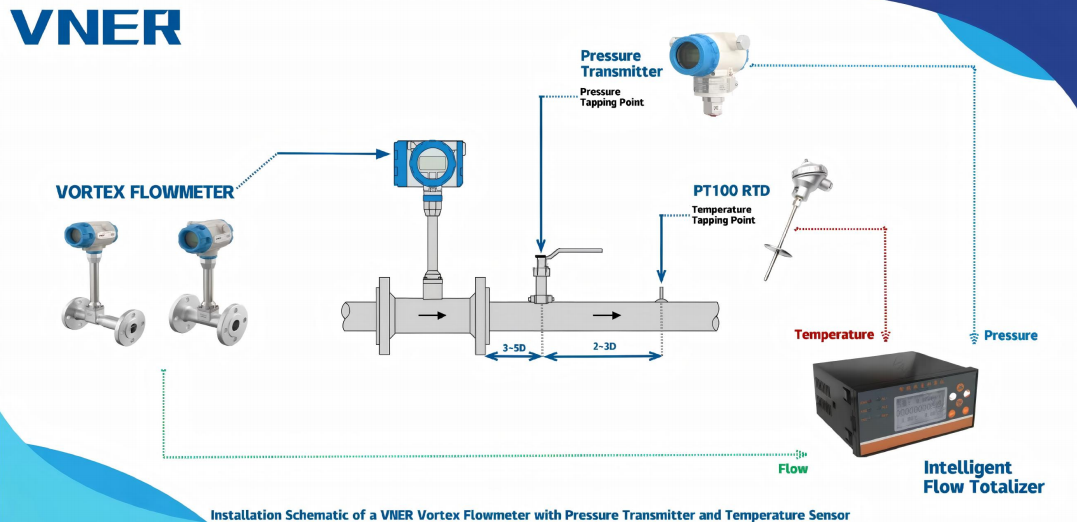
e) Temperature measurement:
- Preferably via built-in thermowell
- Otherwise, locate sensor 2–5D downstream
f) Pressure measurement:
- Preferably via built-in pressure tapping
- Otherwise, locate tapping 2–7D downstream
g) No valves or bypass lines within the straight pipe sections
h) No flow control valves upstream of the meter
i) If gas bubbles or impurities are present, install separators or filters upstream of the straight run
6.Typical Straight Pipe Lengths (Closed Conduit Measurement)
|
Upstream Configuration |
Upstream Length |
Downstream Length |
|
Concentric reducer + fully open gate valve |
≥15D |
≥5D |
|
Single 90° elbow |
≥20D |
≥5D |
|
Two 90° elbows (same plane) |
≥25D |
≥5D |
|
Two 90° elbows (different planes) |
≥40D |
≥5D |
7.Valve Location and Two-Phase Flow Considerations
- Avoid valves or bypasses near the flowmeter
- Pressure-reducing valves may cause phase change downstream
- Two-phase flow (gas in liquid or liquid in gas) must be avoided
- Use gas separators or filters upstream if required
8.Why Eccentric Reducers Should Be Avoided
Coriolis mass flowmeters and positive displacement meters are independent of velocity profile.
All other flowmeters are velocity-profile dependent and require straight upstream and downstream pipe lengths.
Key industry guidance:
- Installation requirements for differential pressure devices shall comply with ISO 5167-1
- For other flowmeters, manufacturer installation guidelines must be strictly followed
- Eccentric reducers severely disrupt velocity profiles and should not be used near velocity-dependent meters
9.Effect of Concentric Reducers on Velocity Profile (Experimental Evidence)
Experimental studies conducted by TNO and Delft Hydraulics using air and water demonstrate:
- A concentric reducer with a diameter ratio D_meter / D_pipe ≈ 0.44 can convert an asymmetric velocity profile into an almost symmetric one (asymmetry < 2%)
- The downstream velocity profile resembles a plug-type velocity profile (PTVP)
- At 5D downstream, the profile remains stable across:
Re = 50,000–250,000 (air)
Re = 20,000–500,000 (water) - Concentric reducers do not eliminate swirl, especially that caused by spatial bends
- De-swirl devices may require ≥6D length, depending on swirl pitch
Summary of Findings
- Concentric reducers significantly improve velocity symmetry
- They do not remove swirl
- Only concentric reducers provide this benefit
- Eccentric reducers introduce severe velocity distortion
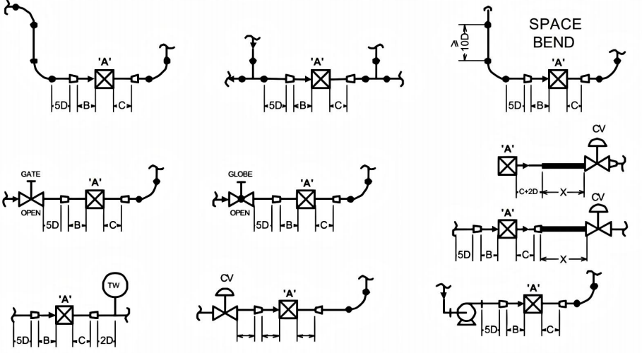
10.Straight Pipe Requirements for Reduced-Diameter Installations
(D_meter / D_pipe ≤ 0.7)
|
Meter Type “A” |
Upstream “B” |
Downstream “C” |
Additional Length for Downstream Control Valve |
|
Vortex |
5 | 5 | 25 |
|
Swirl |
3 | 1 | 25 |
|
Coriolis |
N/A |
N/A |
30 |
|
Ultrasonic |
5 | 5 |
Refer to manufacturer |
|
Therma |
5 | 5 | N/A |
|
Electromagnetic |
5 | 5 |
N/A |
Final Engineering Takeaway
When a vortex flowmeter underperforms, the cause is rarely “instrument quality.”
More often, it is a system-level problem involving:
- Improper diameter selection
- Incorrect reducer type
- Insufficient straight pipe length
- Distorted velocity profile
Correct sizing + concentric reducers + disciplined piping design are the foundation of stable, accurate vortex flow measurement.
If you design the flow field correctly, the instrument will do its job.
We offer all our products and services at international standards.
Products
Contact Information
-

+86-18652789521
+86-18052582295
+86-0514-83633600 / 83633900 -

+86-0514-83633600 / 83633900
-

shawn@vnerflow.com
info@vnerflow.com -

No. 11 Xingye Road, Chenji Town Industrial Park, Yizheng, Yangzhou, China
