
 0
 EN
 English
 عربى
 Español
 русский
If you need any help, please feel free to contact us
Home / News / Industry News / Volumetric Flow Rate Symbol: Q, V-dot, Units and Meter Selection Guide
Volumetric Flow Rate Symbol: Q, V-dot, Units and Meter Selection Guide
A typical project review often starts with a small notation problem. An instrument engineer points to a P&ID line marked Q = 120 m³/h, then opens a vendor datasheet that uses V̇ instead. Both documents describe the same duty, but one uses the plant-standard symbol and the other uses a more formal volume-flow notation. The real question is not which letter looks better. It is whether both documents mean the same volume, at the same time base, under the same reference conditions.
The short answer is simple: the volumetric flow rate symbol is most commonly Q, while V̇ and qV also appear in textbooks, standards, and engineering software. For most plant documents, Q is the practical choice. For academic or standards-heavy work, V̇ makes it clear that volume is being differentiated with respect to time. In both cases, the symbol is only a label. The unit, the fluid phase, and the reference condition decide whether the number is useful.
This article explains what the symbol means, how it differs from mass flow notation, where confusion usually starts, and how to carry the symbol from a calculation sheet into a real flow meter selection. It also covers the checks that matter before a Q value is accepted in a datasheet, a purchase order, or a commissioning report. The aim is practical: a symbol should make communication easier, not create a second layer of interpretation.
What the Volumetric Flow Rate Symbol Means
Volumetric flow rate is the volume of fluid that passes a point or a cross-section per unit time. In its simplest form, the relationship is:
Q = V / t
Here, V is volume and t is time. For steady flow through a pipe, the same idea can be written with cross-sectional area and average velocity:
Q = A × v
If the internal area A is in square metres and the average velocity v is in metres per second, the result is in cubic metres per second. A pipe with an internal area of 0.05 m² and an average velocity of 2 m/s carries 0.1 m³/s, which is 360 m³/h. That calculation is simple, but it shows why the symbol matters: Q links a physical pipe size to a volume-based duty, while velocity describes how fast the fluid moves through it.
The letter Q is widely used because it is short, easy to write on a drawing, and already common in physics and engineering calculations. It is not perfectly unique. In other contexts, Q can mean heat duty, electrical charge, or reactive power. That is why a good document does not rely on the letter alone. It writes the quantity, the unit, and where needed the reference condition next to the symbol.
The notation V̇ uses a dot above the V to show a time derivative. It is precise and common in fluid mechanics and academic writing. Some standards and software tools use qV instead, where the subscript V makes clear that the quantity is volume-based. These are not competing definitions. They are different conventions for the same physical quantity. The table below summarizes the notation that appears most often in flow measurement work.
| Quantity | Common symbol | Alternative notation | Typical SI unit | Practical note |
|---|---|---|---|---|
| Volumetric flow rate | Q | V̇, qV | m³/s | Volume per unit time; for gases, state actual or standard conditions |
| Mass flow rate | ṁ | qm, W in some contexts | kg/s | Requires density or a direct mass measurement principle |
| Average velocity | v | u | m/s | Related to Q by Q = A × v |
| Volume | V | — | m³ | Totalized volume over a period |
| Density | ρ | — | kg/m³ | Links volumetric and mass flow: ṁ = ρ × Q |
| Standard volumetric flow | Qn | QN, Qs | Nm³/h or Sm³/h | Always define the pressure and temperature base |
The last row deserves attention. A gas flow rate written as Nm³/h is not the same as a gas flow rate written as m³/h. The first refers to a defined standard or normal condition; the second usually refers to actual conditions at the meter. If the document does not define the base, the number is incomplete even when the symbol is correct.
Q, V̇, and Mass Flow: What Changes in Practice
Volumetric flow and mass flow are related, but they answer different questions. Volumetric flow tells you how much space the fluid occupies per unit time. Mass flow tells you how much material moves per unit time. The bridge between them is density:
ṁ = ρ × Q
Q = ṁ / ρ
For a liquid, density changes with temperature and composition, but in many plant calculations the change is modest. Water at 20°C has a density near 998 kg/m³. A volumetric flow of 100 m³/h therefore corresponds to about 99.8 t/h. If the temperature moves by a few degrees, the volumetric reading and the mass reading do not separate dramatically. This is why volumetric flow is often accepted for water treatment, cooling water, and many liquid process duties.
For a gas, the situation is different. Gas density changes strongly with pressure and temperature. A mass flow of 1,000 kg/h in a compressed air line represents the same mass whether the line is at 2 bar or 8 bar, but the actual volumetric flow is much smaller at the higher pressure. If one document reports standard volumetric flow and another reports actual volumetric flow, the numbers can differ by a large factor. The process has not changed; the reference condition has.
This is the first place where the volumetric flow rate symbol can mislead. A value of 1,000 Nm³/h and a value of 1,000 m³/h look similar because both use the same number and a volume unit. They are not interchangeable. In gas systems, the symbol should be followed by a clear reference condition, or the project should use mass flow as the common language. For custody transfer, reactor feed, combustion control, and gas billing, mass flow or standard volumetric flow is usually the safer commercial basis.
Volumetric flow is still the right choice for many engineering tasks. It directly supports pipe sizing, pump suction checks, residence time calculations, dilution ratios, and velocity limits. If a plant needs to keep a pipe velocity below 2 m/s to reduce erosion, Q and the pipe area are the natural variables. If a plant needs to know how many kilograms of product entered a tank, mass flow or a density-corrected volume is the better variable. The symbol should follow the purpose, not the other way around.
Where the Symbol Appears in Engineering Documents
In a project, the same flow duty may appear in a P&ID, an instrument index, a datasheet, a calculation sheet, a control narrative, and a commissioning report. Each document has its own conventions. The P&ID may use Q because it is compact. The datasheet may use qV because it follows a standard template. The flow computer may use engineering units only and omit the symbol entirely. The calibration certificate may use actual cubic metres per hour without saying whether the condition is actual or standard.
This is why symbol control is part of document control. A simple legend on the drawing or a note in the datasheet can prevent confusion. For example: Q = actual volumetric flow at meter conditions, m³/h. That single line is more useful than a long glossary. It tells the reader what is measured, where it is measured, and how the unit is defined. If the project also uses standard volumetric flow, give it a different symbol and a different note.
Instrument tags add another layer. A flow transmitter may be tagged FT-101, while the flow indicator on the HMI may be FQI-101. The tag identifies the function, not the physical unit. The displayed value still needs a unit and a reference. An operator who sees a number change from 500 to 450 needs to know whether the change is in m³/h, Nm³/h, kg/h, or a percentage of range. If the HMI uses Q without a unit, the operator is being asked to remember too much.
For calculations, consistency matters more than elegance. If a hydraulic calculation uses Q in m³/h and a velocity check uses Q in m³/s, convert once and label the result. Do not carry two unit systems in the same worksheet without a clear note. Many design errors are not caused by a wrong formula. They are caused by a correct formula applied to a value with the wrong time base or the wrong reference condition.
Units and Conversions That Cause the Most Errors
SI units are straightforward: cubic metres per second for Q, cubic metres for volume, and seconds for time. Plant documents often use more practical units: m³/h for larger liquid lines, L/min for small liquid lines, Nm³/h or Sm³/h for gases, and US gallons per minute for water systems. None of these units is inherently wrong. The risk is mixing them without conversion.
| Unit | Approximate equivalent | Typical use |
|---|---|---|
| 1 m³/s | 3,600 m³/h | Large water, air, and process lines |
| 1 m³/h | 16.667 L/min | General plant liquid flow |
| 1 L/min | 0.06 m³/h | Small liquid dosing and cooling lines |
| 1 US gallon per minute | 0.2271 m³/h | Water systems using US customary units |
| 1 cubic foot per minute | 1.699 m³/h | Air and gas systems using CFM |
A few conversions are worth memorizing because they appear in meetings and field checks. Ten litres per minute is 0.6 m³/h. One hundred US gallons per minute is about 22.7 m³/h. One thousand cubic feet per minute is about 1,699 m³/h. These are simple arithmetic, but they become error-prone when a document mixes minutes and hours, or when a software tool defaults to a different unit than the project specification.
The bigger conversion risk is not between metric and US units. It is between actual and standard volumetric flow. A gas line may be designed for 1,000 Nm³/h, while the meter displays 145 m³/h at 7 bar(g) and 40°C. Both numbers can be correct. If the operator expects 1,000 on the display, the alarm logic may be wrong even though the meter is working properly. The fix is not a new meter. The fix is a clear reference condition and a consistent display convention.
Totalized volume deserves its own check. A flow rate of 50 m³/h for two hours is 100 m³. A totalizer that displays 100 m³ is not the same as a flow display that reads 50 m³/h. During commissioning, confirm whether the control system is receiving a rate signal or a total signal, and confirm the scaling. A factor-of-60 error between minutes and hours can survive a factory test and appear only when the plant starts production.
How to Choose a Flow Meter When the Requirement Is Q
The volumetric flow rate symbol tells you what the process needs. It does not tell you which meter to buy. Two meters can both report Q and still behave very differently because they use different physical principles, have different installation requirements, and respond differently to the fluid. The selection should start with the fluid and the reference condition, then move to the measurement principle, and only then move to the model number.
Start with the fluid and the reference condition
For a liquid, confirm conductivity, viscosity, solids content, temperature, pressure, and whether the liquid is clean or prone to coating. For a gas, confirm composition, pressure, temperature, and whether the required value is actual volumetric flow, standard volumetric flow, or mass flow. For steam, confirm whether it is saturated or superheated and whether temperature and pressure compensation is required. These facts decide more than the meter size.
Conductive liquids are often a good fit for electromagnetic flow meters because they have no moving parts in the flow stream and can handle many dirty or abrasive duties. The meter produces a volumetric output that is linear over a wide range, provided the conductivity is sufficient and the pipe is properly grounded. Across process industries, this principle is common in water, wastewater, pulp and paper, and chemical service. More detail on typical industry applications is available in the process industries overview.
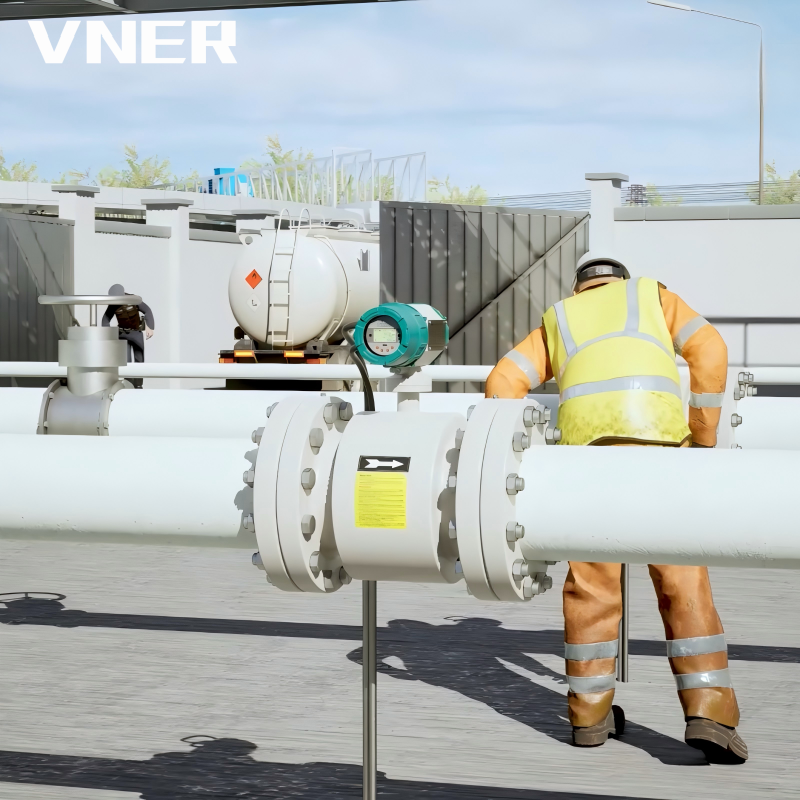 LDG Economy General-Purpose Electromagnetic FlowmeterCost-effective magmeter for conductive liquids from water and wastewater to chemical duties, with no moving parts and broad size and connection options.View Product →
Electromagnetic meters are not a universal answer. They do not measure non-conductive fluids such as many hydrocarbons or gases. They also need careful grounding and a full pipe. If the line runs partially full or the liquid conductivity is very low, another principle may be better. The selection question is not “which meter is best?” It is “which meter makes the required measurement reliably in this line?”
Match the principle to the measurement job
Vortex meters are common for steam, gases, and low-viscosity liquids. They use a bluff body to create vortices, and the shedding frequency is related to velocity. They can be a good fit for medium to large gas lines when the Reynolds number is high enough and vibration is controlled. For a gas duty where pressure and temperature vary, a vortex meter with compensation can report standard volumetric flow or mass flow rather than raw actual volume.
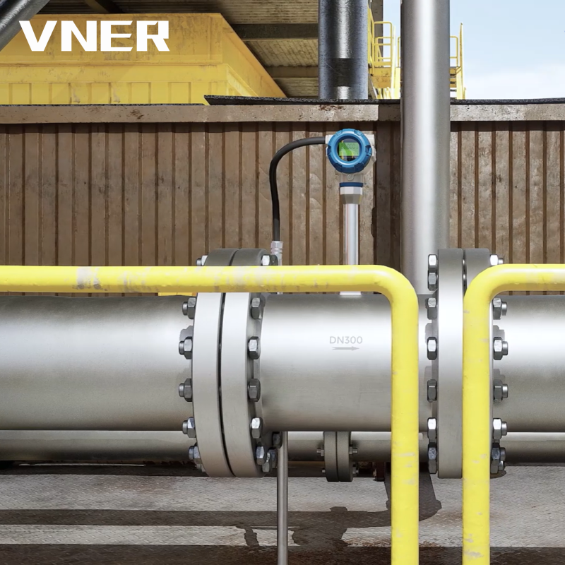 MA80T-TP Series Compensated Vortex Flowmeter for Steam and GasVortex meter with integrated temperature and pressure compensation for steam, compressed gas and utility energy metering, outputting standard volumetric or mass flow.View Product →
Turbine meters are another volumetric option, especially for clean, low-viscosity liquids and some gases. They offer good repeatability and a compact installation, but they have moving parts and are less tolerant of solids, fouling, and over-speed. Swirl meters and positive displacement meters also have a place, but each brings its own installation and maintenance profile. The common mistake is choosing a meter by price before checking the fluid and the turndown.
When the process needs mass flow, density, or concentration as well as flow, a Coriolis meter may be the better fit. It measures mass flow directly and can also provide density and temperature. That makes it useful for custody transfer, chemical dosing, and duties where the product composition changes. A Coriolis meter can report volumetric flow too, but it does so through density. That is a different measurement chain from a purely volumetric meter, and the uncertainty statement should reflect it.
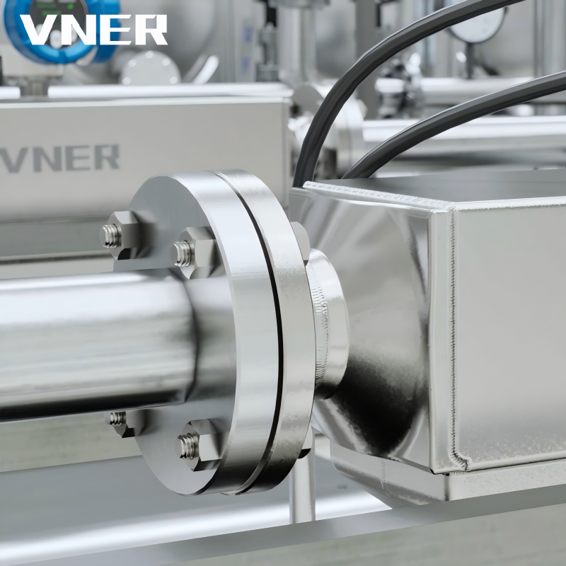 AC Series Coriolis Mass Flowmeter for High-Accuracy MeasurementDirect mass flow, density and temperature measurement for chemical dosing, blending and other duties where composition changes and volumetric meters may fall short.View Product →
Check installation and lifecycle, not just accuracy
Every meter has installation conditions. Some need upstream and downstream straight runs. Some are sensitive to vibration. Some need a full pipe. Some require a minimum back pressure to avoid cavitation. Some are affected by coating on the sensor. A meter that looks excellent on a datasheet can perform poorly if the line layout was fixed before the meter was selected. Bring the meter into the piping review early enough to matter.
Lifecycle matters too. Ask how the meter is calibrated, how the zero is checked, what spare parts are available, and how the output is scaled in the control system. A volumetric meter with a 4–20 mA output and a pulse output may need two different scaling checks. A mass meter with density output may need a separate verification of the density compensation. The symbol Q does not remove those tasks. It only names the quantity that the tasks are protecting.
For project buyers, the most useful supplier is often the one that can explain why one principle fits and another does not. Engineering-driven sizing and selection is more than a catalogue look-up. It connects the process data, the installation, the output signal, and the maintenance plan. The company background page describes this kind of engineering support in more detail: engineering-driven sizing and selection.
Gas Flow: Why the Symbol Alone Is Not Enough
Gas flow is where the volumetric flow rate symbol causes the most commercial confusion. A gas is compressible. Its volume changes with pressure and temperature, so a volumetric flow value without a reference condition is incomplete. If a contract says 1,000 m³/h of natural gas, the next question must be: at what pressure and temperature? If the answer is “at actual conditions,” the mass of gas delivered depends on the line pressure. If the answer is “at standard conditions,” the mass is defined by the standard base.
The approximate relationship between actual and standard volumetric flow can be written as:
Qn ≈ Qa × (Pa / Pn) × (Tn / Ta) × (Zn / Za)
Here, P is absolute pressure, T is absolute temperature, and Z is the compressibility factor. For many low-pressure air calculations, Z can be treated as close to 1. For high-pressure natural gas or process gas, the compressibility factor should not be ignored. The formula is not a substitute for a proper flow computer, but it explains why two correct-looking numbers can differ so much.
Temperature and pressure compensation is not a luxury in gas flow. It is part of the measurement definition. A vortex meter, swirl meter, turbine meter, or differential pressure meter may measure actual volume or a related variable, but the standard volume or mass flow must be calculated from pressure, temperature, and sometimes composition. If the compensation is missing or the base conditions are wrong, the flow computer will produce a precise number with the wrong meaning.
The same issue appears in compressed air systems. A compressor may be rated in Nm³/min or CFM at standard conditions, while the plant meter reads actual m³/h at line pressure. Maintenance teams sometimes compare the two numbers and conclude that the compressor is underperforming. In reality, the meter may be correct and the comparison may be wrong. Before changing a meter or a compressor setting, write the reference condition next to both numbers.
Reading a Datasheet: Six Checks Before You Accept a Q Value
A datasheet can be technically correct and still be commercially dangerous if the reader does not check the context. The following checks are a practical way to review a volumetric flow value before it enters a purchase order, a control philosophy, or a acceptance test.
- Check the unit and time base. Confirm whether the value is m³/h, m³/s, L/min, GPM, or CFM. A time-base error is easy to miss because the number itself may look reasonable.
- Check actual versus standard. For gases, find the pressure and temperature base. If the datasheet says Nm³/h or Sm³/h, confirm the definition. If it says m³/h, confirm whether that is actual volume at the meter.
- Check whether the quantity is volume or mass. A datasheet may use Q in a heading but show kg/h in the table. That is not a symbol problem; it is a quantity problem. Confirm the density basis if a conversion has been made.
- Check the range and turndown. A meter may be accurate at the top of its range and less stable at the bottom. Confirm the minimum and maximum flow, the normal flow, and the units used for each.
- Check the output scaling. A 4–20 mA signal may represent 0–100 m³/h, 0–1,000 m³/h, or a mass range. The same meter can be configured differently. Confirm the scaling in the control system, not only the datasheet.
- Check the calibration and installation basis. A factory calibration may be performed with water or air under reference conditions. The site conditions may include vibration, straight-run limitations, or a different fluid. The uncertainty statement should match the real installation.
These checks are not a substitute for a full engineering review. They are a quick way to catch the errors that survive into commissioning. A Q value is not “approved” because the number matches the process requirement. It is approved when the unit, reference condition, quantity, range, output, and installation basis all match the process requirement.
Installation and Commissioning Details That Affect the Reading
The symbol describes the measurement, but the installation determines whether the meter can deliver it. Many flow problems at startup are not caused by the sensor principle. They are caused by the line layout, the fluid condition, or the signal scaling. The following details are worth checking before the meter is ordered and again before it is commissioned.
- Straight runs and flow profile. Some meters need upstream and downstream straight runs to develop a stable velocity profile. A close-coupled elbow or a partly closed valve can distort the reading even if the meter is calibrated correctly.
- Full pipe and air entrainment. Volumetric meters assume the pipe is full of the intended fluid. Entrained air in a liquid line can increase the apparent volume. A partially full pipe can make a meter read low or become unstable.
- Grounding and electrical environment. Electromagnetic meters need proper grounding to reduce noise. Variable-frequency drives, welding equipment, and poor cable routing can introduce interference. The signal cable should follow the manufacturer’s instructions.
- Vibration and pulsation. Vortex meters and some turbine meters can be affected by vibration or pulsating flow. A pump or compressor nearby may create a periodic disturbance that looks like flow noise.
- Coating and fouling. A dirty sensor surface changes the measurement. Electromagnetic electrodes, ultrasonic transducers, and thermal sensors can all be affected by coating. The maintenance plan should include a cleaning and verification interval.
- Zeroing and scaling. A Coriolis meter may need a zero check under no-flow conditions. A differential pressure meter may need a zero trim. A pulse output may need a K-factor check. These tasks are simple, but they are not optional.
Commissioning should include a comparison between the field reading, the control system reading, and an independent check where possible. The independent check may be a portable clamp-on meter, a tank fill test, or a mass balance. The purpose is not to prove that one instrument is right and the other is wrong. It is to confirm that the unit, the reference condition, and the scaling agree across the whole measurement chain.
If the field reading differs from the control system reading, do not adjust the meter first. Check the scaling, the signal conversion, and the totalizer settings. Many “meter errors” are actually configuration errors. A flow rate of 50 m³/h that becomes 3,000 m³/h in the historian is usually a time-base or scaling problem, not a sensor failure.
A Practical Decision Path for Specifying Q
When a project needs volumetric flow, the following sequence keeps the symbol connected to the real duty. First, write the quantity in words: actual volumetric flow, standard volumetric flow, or mass flow. Second, write the unit and the reference condition. Third, list the fluid properties and the operating range. Fourth, choose the measurement principle. Fifth, confirm the installation and the output scaling. This sequence is simple, but it prevents most of the confusion described earlier.
For a conductive liquid with moderate accuracy requirements, an electromagnetic meter is often a practical starting point. For a clean, low-viscosity liquid with a need for high repeatability, a turbine meter may be considered. For steam or gas with a stable velocity profile, a vortex meter may fit. For mass-based custody transfer or a duty where density matters, a Coriolis meter may be the stronger choice. For a large water line where insertion is impractical, an ultrasonic or electromagnetic solution may be reviewed.
No principle wins everywhere. A meter that is excellent for water may fail on a non-conductive solvent. A meter that is excellent for clean gas may struggle with wet steam. A meter that is excellent for mass flow may be too large or too expensive for a small utility line. The selection should be based on the process, the installation, the maintenance capability, and the commercial purpose of the measurement.
The symbol Q should appear in the specification with enough context to survive a change of supplier. A model number alone does not define the duty. A flow rate alone does not define the meter. A complete specification connects the symbol, the unit, the reference condition, the fluid, the range, the output, and the installation. That is what allows a buyer to compare offers without comparing incomparable numbers.
The volumetric flow rate symbol is small, but it sits at the centre of a larger engineering conversation. Q, V̇, and qV can all be correct. The choice depends on the document convention, not on the physics. The real discipline is to write the unit, the fluid phase, and the reference condition next to the symbol, then to check the measurement principle and the installation against the actual process.
If a value is going into a P&ID, a datasheet, a control system, or a contract, make it unambiguous. State whether the flow is actual or standard. State whether the quantity is volume or mass. Confirm the time base and the scaling. A reader should not have to guess what Q means from context alone. The symbol is there to help, and with a little discipline it does exactly that.


Products
Contact Information
-

+86 18652789521
+86-0514-83633600 / 83633900 -

+86-0514-83633600 / 83633900
-

s@vner.com.cn
katherine@vner.com.cn -

No. 11 Xingye Road, Chenji Town Industrial Park, Yizheng, Yangzhou, China
